Cutting tool for drilling

A technology of cutting tools and cutting edges, which can be used in drilling accessories, manufacturing tools, drilling/drilling equipment, etc., and can solve problems such as unstable drilling

Inactive Publication Date: 2011-10-12
TAEGUTEC
View PDF5 Cites 7 Cited by
  • Summary
  • Abstract
  • Description
  • Claims
  • Application Information

AI Technical Summary

Problems solved by technology

If two or more chips are generated in one flute, smooth evacuation of the chips cannot occur, which often results in unstable drilling

Method used


Image

  • Cutting tool for drilling
  • Cutting tool for drilling
  • Cutting tool for drilling

Examples


Embodiment Construction

[0023] Embodiments of the present invention will now be described in detail with reference to the accompanying drawings.

[0024] In describing the embodiments of the present invention by referring to the drawings, the same reference numerals will be used for the same elements. The description will only focus on the different parts to avoid any redundant description.

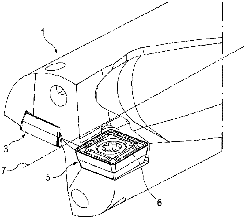
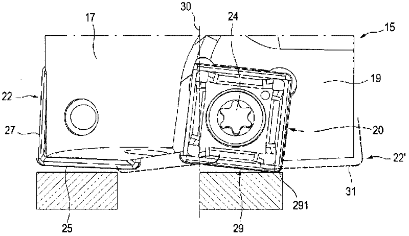
[0025] image 3 One end of a drill bit 15 according to an embodiment of the invention is shown. The drill bit 15 includes a main body 17 , an indexable inner cutting insert 20 and an indexable outer cutting insert 22 . The main body 17 is provided with chip pockets 19 for evacuating chips, namely: chip pockets for evacuating chips generated by cutting of the inner cutting insert 20 and chip pockets for evacuating chips generated by cutting of the outer cutting insert 22 .

[0026] The ends of the chip pocket 19 are provided with insert recesses for receiving the indexable inner cutting insert 20 and outer cu...


PUM


Abstract

The present invention relates to a cutting tool for drilling having inserts in the same shape and being capable of discharging a chip in a chip flute. The cutting tool comprises: a body including a chip flute; and indexable inner and outer cutting inserts disposed in an insert pocket formed at an end of the chip flute. The inner cutting insert is located close to a central axis of the body compared to the outer cutting insert. The inner and outer cutting inserts have the same shape and include lower cutting edges for depth cutting during drilling. The lower cutting edge of the inner cutting insert is disposed lower than the lower cutting edge of an imaginary cutting insert at a position where the inner cutting insert is overlapped with the imaginary cutting insert where the outer cutting insert is rotated by approximately a half-turn relative to the central axis.

Description

technical field [0001] In general terms, the present invention relates to cutting tools for drilling. More specifically, the present invention relates to a cutting tool for drilling that includes inner and outer indexable cutting inserts disposed in a chip flute formed in a chip flute. in the insert pocket at the end. Background technique [0002] In general, drills can be classified into solid drills and disposable drills depending on whether a cutting edge is formed integrally or separately from a drill body. Specifically, the throw away drill is provided with an indexable cutting insert disposed in an insert pocket formed in the end of the drill body. In disposable drills, the cutting inserts are mounted symmetrically or asymmetrically with respect to the central axis of the drill body. [0003] figure 1 and 2 A conventional throwaway drill is shown in which the cutting inserts are mounted asymmetrically with respect to the central axis of the drill body. Such as f...

Claims


Application Information

Patent Timeline
Patent Type & Authority Applications(China)
IPC IPC(8): B23B51/02
CPCY10T408/9095B23B51/00B23B51/02B23B51/08
Inventor 金珉求
Owner TAEGUTEC
Why Eureka
Try Eureka