
Construction method of a drilling device for complex high and steep slopes

A drilling device and technology for high and steep slopes, applied in the field of geotechnical engineering, can solve problems such as hole position deviation, drill pipe breakage, and increased project cost, and achieve enhanced stability and safety performance, high work efficiency, and mobility strong effect

Active Publication Date: 2021-09-07
DALIAN UNIV OF TECH
View PDF7 Cites 2 Cited by
  • Summary
  • Abstract
  • Description
  • Claims
  • Application Information

AI Technical Summary

Problems solved by technology

However, the nature of the slope is more complicated (1) The stratum is complex, part of the surface of the slope is soil, and after a certain depth, it is rock mass
(2) Complex slope
Therefore, the traditional drilling technology has the following problems: (1) due to changes in the soil layer, it is necessary to frequently replace the drilling equipment
(2) The soil is soft and the vegetation is dense, so scaffolding construction is not possible
(3) The existing movable drilling platform is too large to travel through the jungle
(4) The existing movable drilling platform is four-wheel type, it is difficult to travel on uneven roads, and the stability is poor when drilling
However, this type of solution has the following problems: (1) It takes a lot of time to replace, transport, assemble and check equipment, especially in the case of high slope support operations, it is very difficult to replace equipment, which increases the construction period
(2) Replacing or leasing different drilling equipment according to different formation conditions, which virtually increases the project cost
(3) Replacement and shifting of tools may easily cause hole position deviation, resulting in frequent drill pipe breakage accidents

Method used


Image

  • Construction method of a drilling device for complex high and steep slopes
  • Construction method of a drilling device for complex high and steep slopes
  • Construction method of a drilling device for complex high and steep slopes

Examples


Embodiment 1

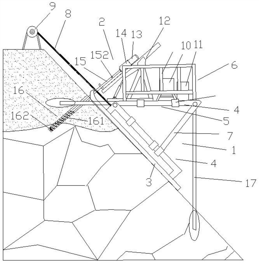
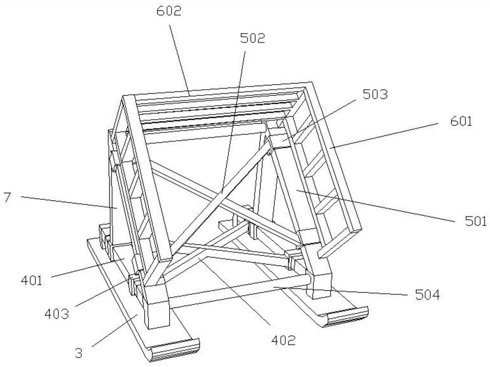
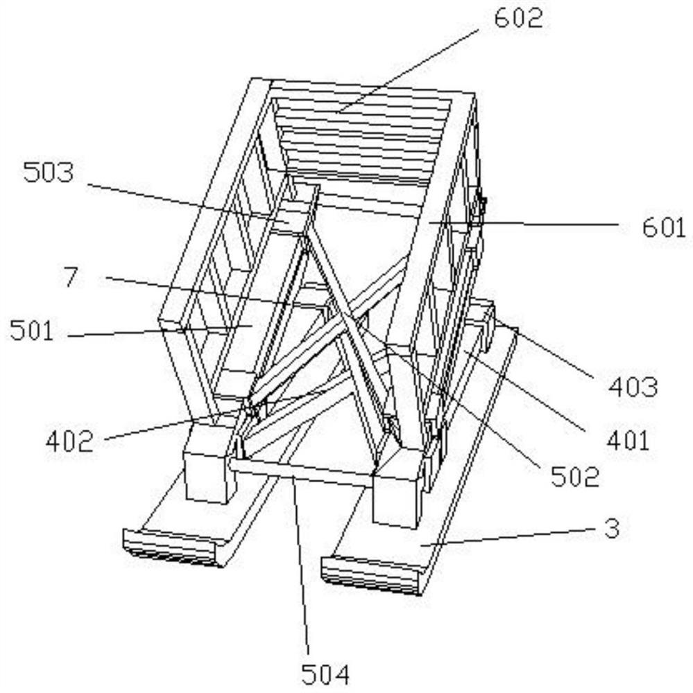
[0042] Such as Figure 1-5Shown, a kind of construction method of the drilling device of complex high steep slope, described drilling device comprises drilling machine support 1, drilling machine base 12 and drilling machine 2; Described drilling machine support 1 comprises slide plate 3, The chassis 4 and the platform 5 are arranged on the skateboard 3; the chassis 4 includes two chassis longitudinal steel pipes 401 parallel to the skateboard and a chassis cross steel pipe 402 sleeved on the chassis longitudinal steel pipes 401, and the chassis sleeve 403 passes through the The steel pipe 401 slides to realize the opening and closing of the cross steel pipe 402 of the chassis. The longitudinal steel pipe 401 of the chassis is fixedly connected to the slide plate 3. The platform 5 includes two platform longitudinal steel pipes 501 parallel to the slide plate 3 and a platform socketed on the platform longitudinal steel pipe 501. The cross steel pipe 502 and the front and rear t...


PUM


Abstract

The invention discloses a construction method of a drilling device for complex high and steep slopes. The drilling device comprises a drilling machine support, a drilling machine base and a drilling machine. The drilling machine bracket includes a slide plate, on which there is a chassis, the front end of the chassis is hingedly connected with the front end of the platform, the supporting member is hingedly connected with the platform, and connected with the chassis fastener, and the width of the chassis and the platform can be adjusted; the drilling machine includes a power distribution system , air pressure system, gears, rock drilling components, soil drilling components, drill pipes and drill bits; construction methods include: 1) Pull the drilling machine bracket to the designated position; 2) Expand the bracket and lock it; 3) Adjust the chassis and platform Angle; 4) Install the drilling machine; 5) Start drilling. The invention solves the problem of difficult drilling of complex high and steep slopes, can be adapted to various rock and soil strata, and can deal with complex slope conditions such as unevenness and lush forests. It is flexible in action, safe and reliable in performance, and can fully cope with existing Reinforcement works for complex high and steep slopes.

Description

technical field [0001] The invention belongs to the technical field of geotechnical engineering, and in particular relates to a construction method of a drilling device for complex high and steep slopes. Background technique [0002] In the natural environment, there are a large number of dangerous slopes, which are always facing the possibility of instability and landslides. In order to ensure the safety of people's lives and properties, such dangerous slopes need to be artificially reinforced. However, the nature of the slope is more complicated (1) The stratum is complex, part of the surface layer of the slope is soil, and after a certain depth, it is rock mass. (2) The slope is complex. The vegetation on the slope is dense, the slope is uneven, and the soil is soft. Therefore, the traditional drilling technology has the following problems: (1) due to changes in the soil layer, frequent replacement of drilling equipment is required. (2) The soil is soft and the vegeta...

Claims


Application Information

Patent Timeline
Patent Type & Authority Patents(China)
IPC IPC(8): E21B7/00E21B15/00E21B3/02E21B6/02
CPCE21B3/02E21B6/02E21B7/00E21B15/00
Inventor 张丽华高幸陈湘生贾金青涂兵雄朱彦鹏王旭春周同和廖小平
Owner DALIAN UNIV OF TECH
Learn More