Device and method for controlling a resonant ultrasound piezoelectric injector

A control device and injector technology, which can be used in piezoelectric device or electrostrictive device components, electrical control, engine control, etc., and can solve problems such as heating boost stage and low efficiency

Inactive Publication Date: 2011-10-12
RENAULT SA
View PDF3 Cites 3 Cited by
  • Summary
  • Abstract
  • Description
  • Claims
  • Application Information

AI Technical Summary

Problems solved by technology

However, this large size leads to the selection of very large and very expensive transistors and creates inefficiencies and thus also heats up the boost stage 2

Method used


Image

  • Device and method for controlling a resonant ultrasound piezoelectric injector
  • Device and method for controlling a resonant ultrasound piezoelectric injector
  • Device and method for controlling a resonant ultrasound piezoelectric injector

Examples


Embodiment Construction

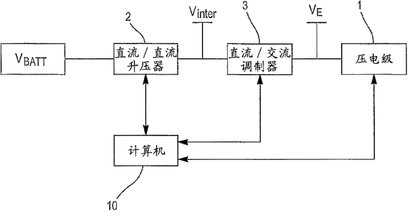
[0039] The present invention is based on having already referred to figure 1 Illustrates the controls of the boost stage and modulation stage.

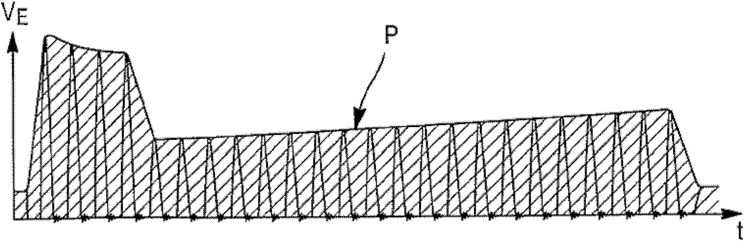
[0040] The invention proposes to modify the modulation stage of the above-mentioned control device so as to be able to vary the amplitude of the field voltage supplied at the output of this stage (ie the input of the associated injector) with a large dynamic range. refer to image 3 To illustrate this principle of changing the amplitude of the excitation voltage envelope of the injector with a large dynamic range, where image 3 shows an excitation voltage V suitable for allowing particularly flexible injection control E The profile P of the envelope.

[0041] Therefore, in addition to performing the modulation by the modulation stage, it also involves being able to modulate the amplitude of the excitation voltage peak of the injector, preferably at the resonance frequency of the injector, part of which requires the generation of t...


PUM


Abstract

The invention relates to a device for controlling a resonant ultrasound piezoelectric stage (1), including: a first stage (2) of increasing a DC voltage (VBATT) to an intermediate DC voltage (Vinter), a second modulation stage (3), including an inductor (Lp) connected to the intermediate DC voltage and a first switching transistor (M) for selectively controlling a phase of charging the inductor and a phase of transferring the energy stored in the inductor in response to a first stream of command pulses (Vl), to generate an excitation voltage (VE) of the piezoelectric stage, characterised in that the second stage includes a second switching transistor (M') connected in series between the drain of the first transistor and a terminal of the inductor, suitable for limiting the energy stored in the inductor during the charging phase in response to a second stream of command pulses (V2), so as to reduce the amplitude of the excitation voltage.

Description

technical field [0001] The invention relates to the field of electronic injection of internal combustion engines of motor vehicles. More specifically, the present invention relates to apparatus and methods for controlling a resonant ultrasonic piezoelectric stage fuel injector. Background technique [0002] exist figure 1 The known structure of such a control device is schematically shown in . [0003] This device is designed to control at least one resonant ultrasonic voltage level 1 of the injector, controlled by a control computer 10 and a DC voltage source V BATT (eg vehicle battery) to electronically control the injectors. The controls include: [0004] - the first stage 2 for applying the DC voltage V BATT boost to generate an intermediate DC voltage V inter (hundreds of volts, such as 250 volts), [0005] - Second stage 3 for modulating the intermediate DC voltage V inter , by the intermediate DC voltage V inter Provides and is suitable for generating the AC ...

Claims


Application Information

Patent Timeline
IPC IPC(8): F02D41/20H01L41/04
CPCF02D41/2096F02D2041/2003F02D2041/2048H02N2/065
Inventor C·努瓦尔
Owner RENAULT SA
Why Eureka
Try Eureka