Plate type valveless piezoelectric pump and working method thereof

A valveless piezoelectric pump, piezoelectric technology, applied in variable capacity pump components, pumps with flexible working elements, pumps, etc., can solve the problems of small output flow, serious backflow, and difficulty in miniaturization, so as to reduce liquid Effects of reflow, increased output pressure, and ease of miniaturization

Pending Publication Date: 2019-12-20
NANJING UNIV OF AERONAUTICS & ASTRONAUTICS
View PDF12 Cites 0 Cited by
  • Summary
  • Abstract
  • Description
  • Claims
  • Application Information

AI Technical Summary

Problems solved by technology

[0003] The power of the piezoelectric pump to transport liquid comes from the deformation caused by the inverse piezoelectric effect of the piezoelectric substrate; from the perspective of whether there is a valve, the piezoelectric pump can be divided into a valve piezoelectric pump and a valveless piezoelectric pump. Valved piezoelectric pumps have the problem of complex structure and difficult miniaturization, and under high-frequency conditions, the one-way valve cannot track the action and cannot transport liquid; valveless piezoelectric pumps are easy to miniaturize, and there is no High-frequency working conditions cannot track the action; however, valveless piezoelectric pumps generally have the problems of small output flow, low output pressure, and serious backflow

Method used


Image

  • Plate type valveless piezoelectric pump and working method thereof
  • Plate type valveless piezoelectric pump and working method thereof
  • Plate type valveless piezoelectric pump and working method thereof

Examples


Embodiment Construction

[0031] The present invention will be described in further detail below in conjunction with the accompanying drawings.

[0032] This invention may be embodied in many different forms and should not be construed as limited to the embodiments set forth herein. Rather, these embodiments are provided so that this disclosure will be thorough and complete, and will fully convey the scope of the invention to those skilled in the art.

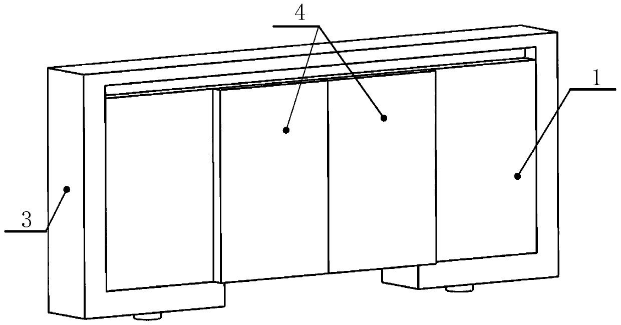
[0033] Such as figure 1 As shown, the present invention discloses a plate-type valveless piezoelectric pump, which includes a piezoelectric substrate 1, a flexible rectangular bar 2, a pre-pressure frame 3 and a piezoelectric ceramic sheet 4, and the four piezoelectric ceramic sheets 4 are in piezoelectric Both sides of the substrate are distributed symmetrically, the two piezoelectric ceramic sheets on the same side are not in contact, and the piezoelectric substrate material is metal.

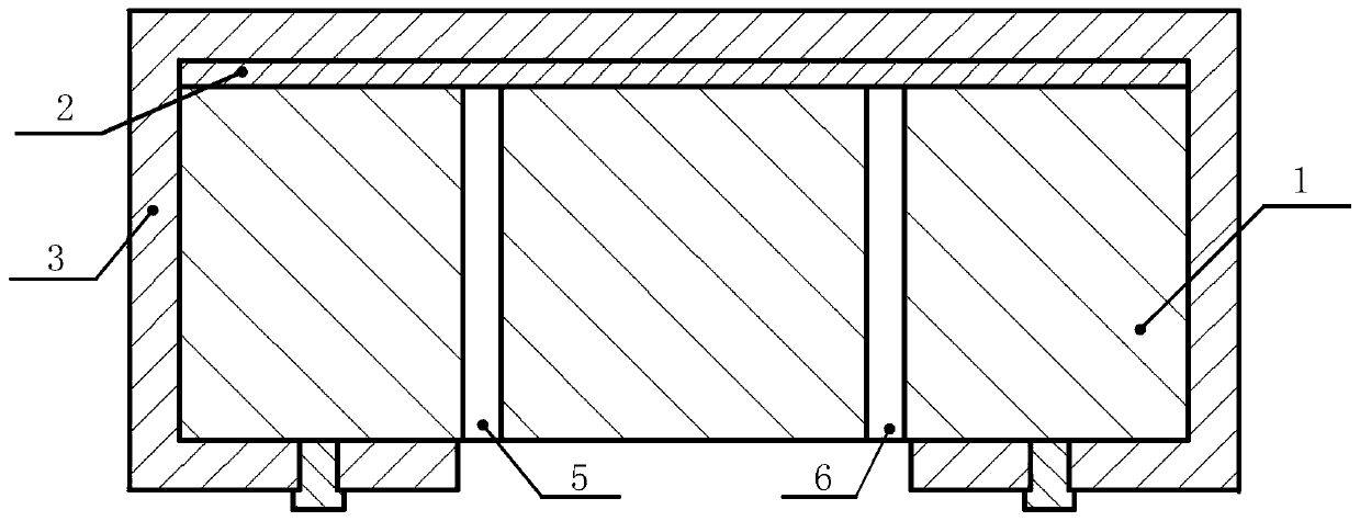
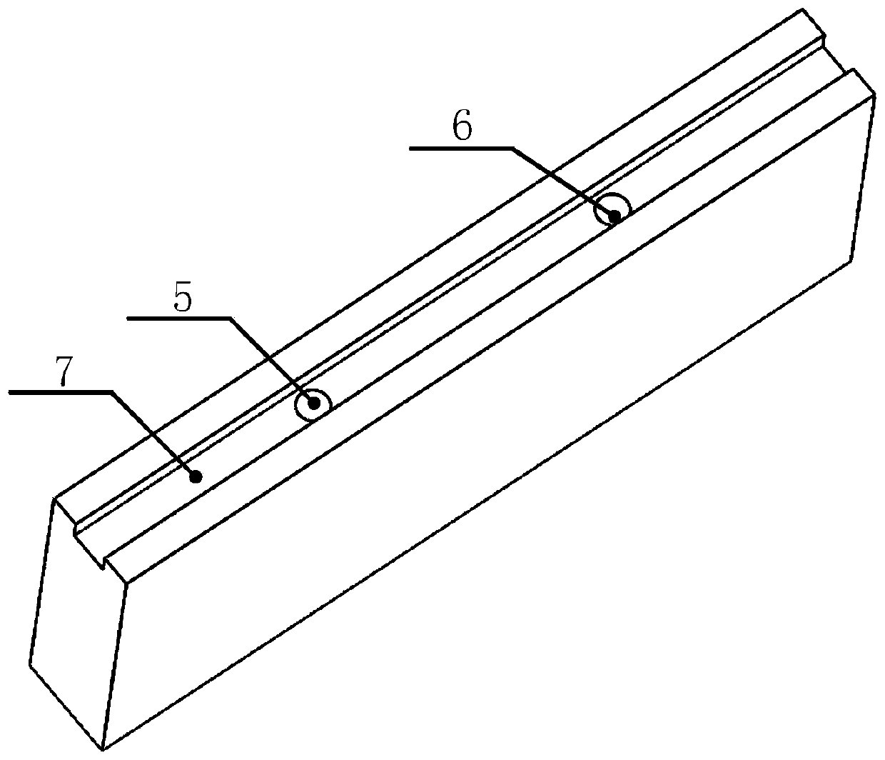
[0034] Such as figure 2 , image 3 , Figure 4 As shown, th...


PUM


Abstract

The invention discloses a plate type valveless piezoelectric pump and a working method thereof. The plate type valveless piezoelectric pump comprises a plate type piezoelectric base body, a flexible rectangular strip, a pre-pressure frame and piezoelectric ceramic sheets; the piezoelectric base body is of a rectangular plate structure, the upper end face is provided with a rectangular groove, andthe lower end face is provided with a flow inlet hole and a flow outlet hole; the pre-pressure frame is of a frame structure with an opening, and the upper inner wall is provided with a convex rectangular structure which is used for pressing the flexible rectangular strip; the four rectangular piezoelectric ceramic sheets are symmetrically arranged on the two sides of the piezoelectric base body;and during working, the flow inlet hole is filled with liquid, same-frequency equal-amplitude electric signals with the phase difference of pi/2 are adopted to excite the four piezoelectric ceramic sheets correspondingly, the piezoelectric base body generates second-order bending vibration and first-order longitudinal vibration, the second-order bending vibration and the first-order longitudinal vibration are coupled to form standing wave motion, a movable cavity is formed at the interface matched with the flexible rectangular strip, and the liquid is transported from the flow inlet hole to the flow outlet hole. The pump has the advantages that the structure is simple, the output flow is high, the backflow can be effectively reduced, and miniaturization can be realized.

Description

technical field [0001] The invention relates to the technical field of fluid machinery, in particular to a plate-type valveless piezoelectric pump and a working method thereof. Background technique [0002] Compared with traditional pumps, piezoelectric pumps have been widely used in biomedical, aerospace, microelectronics cooling and other fields due to their advantages of precise control of micro flow, simple structure, no noise, low power, no electromagnetic interference and no electromagnetic interference. widely used. [0003] The power of the piezoelectric pump to transport liquid comes from the deformation caused by the inverse piezoelectric effect of the piezoelectric substrate; from the perspective of whether there is a valve, the piezoelectric pump can be divided into a valve piezoelectric pump and a valveless piezoelectric pump. Valved piezoelectric pumps have the problem of complex structure and difficult miniaturization, and under high-frequency conditions, the...

Claims


Application Information

Patent Timeline
Patent Type & Authority Applications(China)
IPC IPC(8): F04B43/04F04B13/00F04B53/00
CPCF04B43/046F04B13/00F04B53/00
Inventor 尹永康王亮金家楣刘瑞王方一
Owner NANJING UNIV OF AERONAUTICS & ASTRONAUTICS
Why Eureka
Try Eureka