Lead screw feeding platform with loading assistant support

A technology of auxiliary support and lead screw, which is applied to workbenches, manufacturing tools, large-scale fixed members, etc., can solve the problems of collision between moving parts and support blocks, affecting the movement accuracy of the workbench, and unable to guarantee the support effect, etc., to reduce the support Distance and structure settings are simple and ingenious, and the effect of compact structure

Active Publication Date: 2013-03-06
TSINGHUA UNIV
View PDF5 Cites 0 Cited by
  • Summary
  • Abstract
  • Description
  • Claims
  • Application Information

AI Technical Summary

Problems solved by technology

The fixed-point temporary support device can only act as a temporary support, and the position of the support device must be readjusted when the workbench moves for a certain distance, which not only limits the screw stroke, but also cannot be used under high-speed conditions.
The follow-up support device of the partition connects the support plate with the auxiliary nut, and mounts it on the two guide rails, which can play the role of follow-up support for the screw, but when the two guide rails are not parallel in the vertical direction When, can not guarantee a good support effect
The connecting rod slider support device connects the two supporting blocks through the connecting rod. The supporting block can slide on the screw, and the moving part (nut table) pushes the supporting block on one side to slide. In order to reduce the collision, a buffer is set. The rod drives the support device on the other side to move together, which serves as a follow-up support, but the support block of the device is in sliding contact with the lead screw, and the friction coefficient is large, and the moving parts and the support block often collide, which will also affect Movement accuracy of the table

Method used


Image

  • Lead screw feeding platform with loading assistant support
  • Lead screw feeding platform with loading assistant support
  • Lead screw feeding platform with loading assistant support

Examples


Embodiment Construction

[0012] The present invention will be described in detail below with reference to the drawings and embodiments.

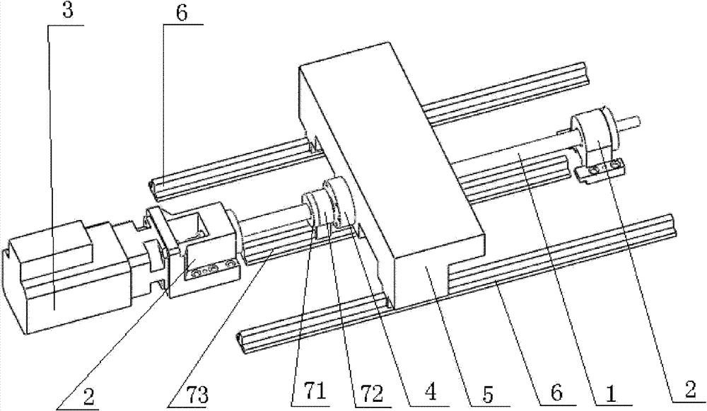
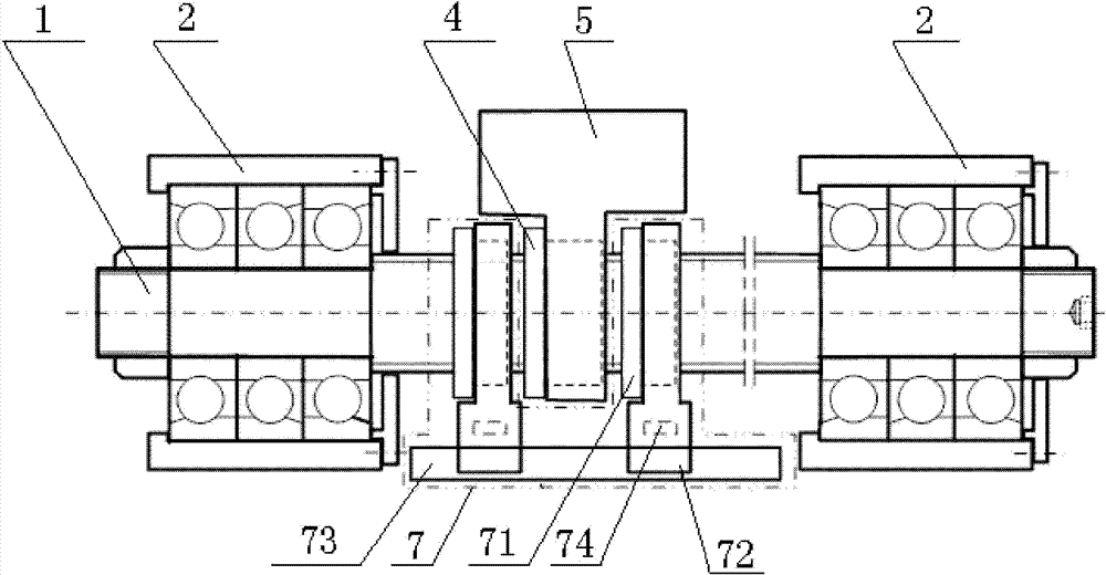
[0013] Such as figure 1 , figure 2 As shown, the present invention includes a lead screw 1, both ends of the lead screw 1 are provided with bearing support devices 2, one end of the lead screw 1 is connected to the output shaft of the driving motor 3. The screw 1 between the two bearing support devices 2 is threadedly connected with a workbench drive nut 4, the workbench drive nut 4 is provided with a workbench 5, and a guide rail parallel to the screw 1 is provided on both sides of the bottom of the workbench 5 respectively 6. The workbench 5 can slide on two guide rails 6 and supports the load on the workbench 5 through the guide rails 6. A follow-up auxiliary support device 7 for restraining the bending of the lead screw 1 is arranged between the two bearing support devices 2.

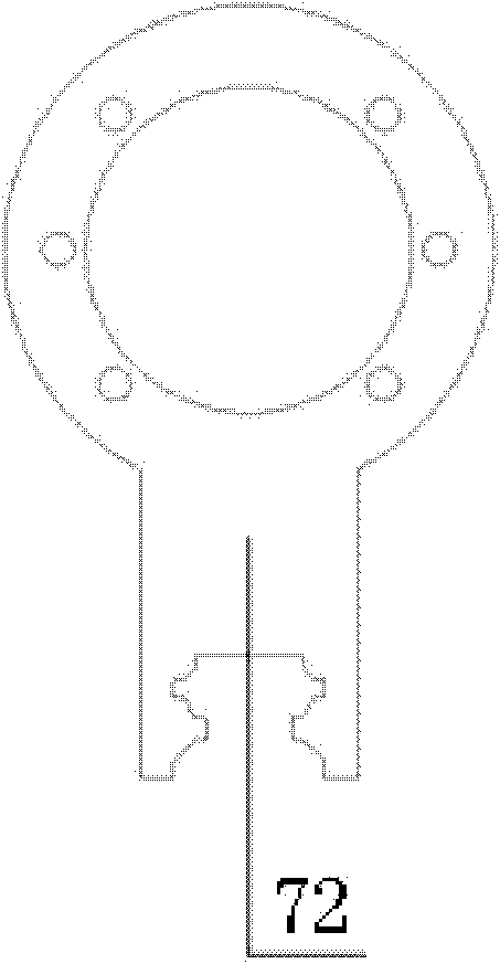
[0014] Such as figure 2 , image 3 As shown, the follow-up auxiliary support device 7 ...


PUM


Abstract

The invention relates to a lead screw feeding platform with a loading assistant support, which is characterized in that a motor drives a lead screw, two ends of the lead screw are fixedly supported by a bearing; the lead screw and a workbench driving nut form a rolling spiral kinematic pair; the workbench driving nut is provided with a workbench; the bottom end of the workbench is provided with aguide rail; a loading assistant support device is arranged between two bearing supporting devices; the loading assistant support device comprises assistant driving nuts respectively arranged on two sides of the workbench driving nut; two assistant driving nuts are connected with the lead screw; each assistant driving nut is respectively fixedly connected with a slide block; the lower parts of thetwo slide block form a moving pair with the assistant supporting guide rail; and two slide blocks are respectively provided with a pressure sensor. In the lead screw feeding platform, real-time loading can be realized by the loading assistant support, the radial stress situation of the lead screw can be detected to reflect the nonparallelism of the vertical direction of the guide rail to effectively inhibit the flexural deformation of the lead screw due to radial stress, thus, the lead screw feeding platform can be widely applied to the horizontal large-route high-speed feeding platform of a machine tool lead screw.

Description

Technical field [0001] The invention relates to a lead screw feeding platform, in particular to a lead screw feeding platform with a follow-up auxiliary support. Background technique [0002] Generally, although the screw in the horizontal high-speed feed platform of the large-stroke screw adopts a fixed support method at both ends, because the screw is relatively long and slender, the screw will produce under the action of its own weight or external radial force. More serious bending deformation; under high-speed running conditions, the bending part of the lead screw will be subjected to greater centrifugal force, which further increases the bending deformation of the lead screw. Moreover, during the actual installation and operation, if the two guide rails supporting the workbench are not parallel in the vertical direction, the lead screw will locally bear a relatively large radial force. However, for the thin filament supported only at both ends The bending deformation caused...

Claims


Application Information

Patent Timeline
Patent Type & Authority Patents(China)
IPC IPC(8): B23Q1/50B25H1/02
Inventor 赵彤王仁彻祝莉平叶佩青张辉
Owner TSINGHUA UNIV
Why Eureka
Try Eureka