
Image compression system based on optical contourlet transformation

A contourlet transform and image compression technology, applied in the field of image processing, can solve the problems of constraints, slow compression, and difficulty in meeting the real-time performance of image compression, and achieve the effect of promoting development, improving image compression speed, and avoiding light energy loss.

Inactive Publication Date: 2011-10-19
CHONGQING UNIV
View PDF3 Cites 2 Cited by
  • Summary
  • Abstract
  • Description
  • Claims
  • Application Information

AI Technical Summary

Problems solved by technology

[0005] However, the huge amount of calculations in the application of contourlet transform based on electrical numerical calculations restricts its further promotion. The image compression technology based on electrical contourlet transform has the obvious disadvantage of slow compression speed, and it is difficult to meet the real-time requirements of image compression. Require

Method used


Image

  • Image compression system based on optical contourlet transformation
  • Image compression system based on optical contourlet transformation
  • Image compression system based on optical contourlet transformation

Examples


Embodiment 1

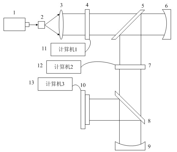
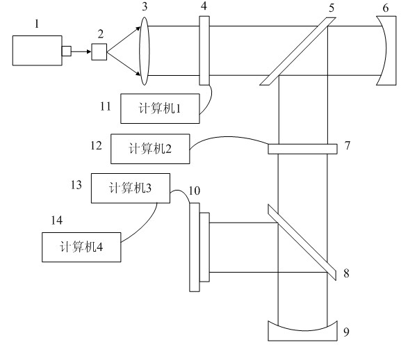
[0032] Embodiment 1: In the optical contourlet transformation module, the helium-neon laser 1 is located at 22 cm in front of the pinhole filter 2, and the pinhole filter 2 is located at the front focal plane of the collimating lens 3, which is installed at 32 cm behind the collimating lens 3 The first electrical addressing spatial light modulator 4, the first optical splitter 5 is installed at 22 cm behind the first electrical addressing spatial light modulator 4, and the first Fourier reflector 6 is installed behind the first optical splitter 5 , the distance between the first electrically addressable spatial light modulator 4 and the first Fourier reflector 6 is equal to the focal length of the first Fourier reflector 6, and the first beam splitter 5 is installed below the first Two electrical addressing spatial light modulators 7, the distance between the first Fourier reflector 6 and the first beam splitter 5 is the same as the distance between the first beam splitter 5 an...

Embodiment 2

[0039] Embodiment 2 has the same structure and method as Embodiment 1, except that in Embodiment 2, the He-Ne laser 1 is located at 24 cm in front of the pinhole filter 2, and the first electrical addressing spatial light modulation is installed at 34 cm behind the collimating lens 3. 4, the first optical splitter 5 is installed 24 cm behind the first electrical addressable spatial light modulator 4, and the second optical splitter 8 is installed 24 cm below the second electrical addressable spatial light modulator 7.

Embodiment 3

[0040] Embodiment 3 has the same structure and method as Embodiment 1, except that in Embodiment 3, the He-Ne laser 1 is located 20 cm in front of the pinhole filter 2, and the first electrical addressing spatial light modulation is installed at 30 cm behind the collimator lens 3. 4, the first optical splitter 5 is installed 20 cm behind the first electrical addressable spatial light modulator 4, and the second optical splitter 8 is installed 20 cm below the second electrical addressable spatial light modulator 7.

[0041] Apply the optical contourlet transformation module to realize the contourlet transformation of the input image, such as figure 2 As shown, the He-Ne laser 1 passes through the pinhole filter 2 and the collimator lens 3 to form parallel light to irradiate on the first electrical addressing spatial light modulator 4, and the input image is loaded to the first electrical addressing spatial light modulator 4 under the control of the first computer 11. On the ad...


PUM


Abstract

The invention discloses an image compression system based on optical contourlet transformation, belonging to the technical field of image processing. The system comprises an optical contourlet transformation module, a quantification module and a statistical coding module. An image compression method comprises the following steps of: performing contourlet transformation on an input image by using the optical contourlet transformation module to obtain a numerical value result of the contourlet transformation of the input image; quantifying the numerical value result of the contourlet transformation of the input image by using the quantification module to obtain a quantification result of the numerical value result of the contourlet transformation of the input image; and coding the quantification result of the numerical value result of the contourlet transformation of the input image by using the statistical coding module to obtain a compression coding result of the input image. The image compression method disclosed by the invention can be applied to the fields of distance learning, tele-medicine, image monitoring, digital photography, traffic monitoring and the like. Compared with the conventional image compression method, the method has the advantage that: the image compression speed can be increased.

Description

technical field [0001] The invention belongs to the technical field of image processing, and relates to image compression technology, in particular, an image compression system based on optical contourlet (Contourlet) transformation. Background technique [0002] The development of modern image and multimedia communication services requires a large amount of storage, recording and transmission of various images. The only way to solve this problem is to digitize the image. Image signal digitization has many advantages that analog signals do not have, such as: it is easy to use channel coding technology to improve the reliability of transmission; it is easy to use time division multiplexing to combine with other communication services; it is easy to encrypt and improve security. However, the amount of data after digitization is too large to be directly stored and transmitted, so it is imperative to implement data compression on digital images. Image coding is a compression c...

Claims


Application Information

Patent Timeline
Patent Type & Authority Applications(China)
IPC IPC(8): G06T9/20G02B27/10G02B17/02
Inventor 韩亮蒲秀娟余月华吴江洲张博为李禅飞
Owner CHONGQING UNIV
Learn More