Under-voltage supervision circuit
A technology for monitoring circuits and voltage dividing resistors, applied in circuit devices, protection for undervoltage or no voltage response, emergency protection circuit devices, etc., can solve the problems of complex structure of undervoltage monitoring circuits and poor monitoring effects, etc. Achieve the effects of accurate monitoring prompt results, simple structure, and convenient operation
- Summary
- Abstract
- Description
- Claims
- Application Information
AI Technical Summary
Problems solved by technology
Method used
Image

Examples
Embodiment 1
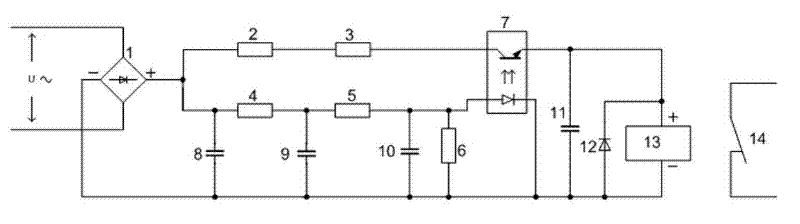
[0020] figure 1 It is a single-phase power supply monitoring circuit diagram of the present invention, which includes a sub-rectifier bridge 1, a current limiting resistor (2, 3), a voltage dividing resistor (4, 5), a reference resistor 6, an optocoupler device 7, and contacts driven by a relay coil 14. The freewheeling diode 12 of the relay coil 13, the filter capacitor (8, 9, 11) and the decoupling capacitor 10. The AC power supply to be monitored is connected between the AC nodes of the rectifier bridge, and two branches are connected in parallel between the positive and negative stages of the output terminal of the rectifier bridge. The first branch is a relay branch, and the second is a voltage dividing monitoring branch. An optocoupler device 7 is arranged between the two branches. The monitoring voltage dividing branch and the optocoupler device 7 constitute a monitoring control unit. The current-limiting resistors (2, 3) and the relay coil 13 are connected in series ...
Embodiment 2
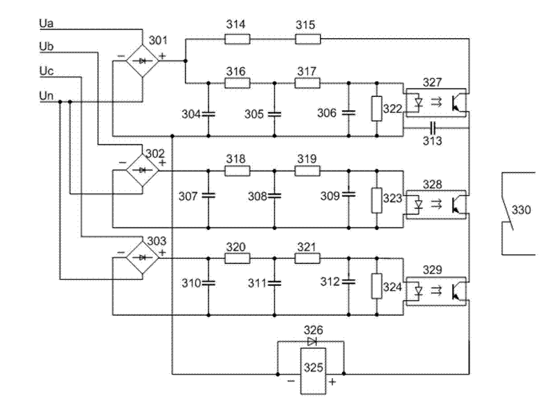
[0024] like Figure 4 As shown, the three phase voltages of the AC voltage are respectively connected to the input ends of the rectifier bridges 401, 402, and 403, and the output of each rectifier bridge is connected to a separate monitoring control unit and a relay branch, and the monitoring control unit and the relay branch Same as Embodiment 1. The relay coil 433 of the A phase controls the relay contact 436 to indicate whether the A phase is undervoltage; the B phase relay coil 434 controls the relay contact 437 to indicate whether the B phase is undervoltage; the C phase relay coil 435 controls the relay contact 438, Indicates whether phase C is undervoltage. Similarly, the line voltage of the three-phase AC can also be connected to the input terminal of the rectifier bridge, so as to realize the separate monitoring of the three-phase line voltage.
Embodiment 3
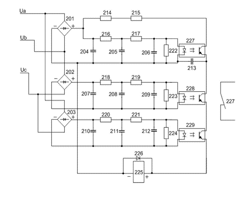
[0026] like figure 2 As shown, the circuit can monitor the voltage loss of the line voltage of the three-phase power supply, and it includes a rectifier bridge (201, 202, 203) for rectifying the AC voltage, three monitoring control units and a relay branch. The three monitoring and control units have the same circuit structure as that of the first embodiment. Each line voltage corresponds to a rectifier bridge (201, 202, 203), the line voltage (Ua-Ub) is added to the rectifier bridge 201, the relay branch is connected to the output end of the rectifier bridge 201, and the relay branch is connected in series with a current-limiting resistor (214, 215) and relay coil 225; three monitoring control units, each corresponding to a line voltage, each monitoring control unit includes an optocoupler device and a voltage division monitoring branch, each voltage division monitoring branch connected in parallel to the output end of the corresponding line voltage rectifier bridge, includ...
PUM
 Abstract
Description
Claims
Application Information
 - R&D
- Intellectual Property
- Life Sciences
- Materials
- Tech Scout
- Unparalleled Data Quality
- Higher Quality Content
- 60% Fewer Hallucinations
Browse by: Latest US Patents, China's latest patents, Technical Efficacy Thesaurus, Application Domain, Technology Topic, Popular Technical Reports.
© 2025 PatSnap. All rights reserved.Legal|Privacy policy|Modern Slavery Act Transparency Statement|Sitemap|About US| Contact US: help@patsnap.com