Method and system for determining topology structure of passive optical network

A technology of passive optical network and topology structure, applied in the field of communication, can solve the problems of calculation, inability to send luminous power information, inconvenient OLT management of ONU, etc., and achieve the effect of easy management

Inactive Publication Date: 2015-06-03
ZTE CORP
View PDF7 Cites 0 Cited by
  • Summary
  • Abstract
  • Description
  • Claims
  • Application Information

AI Technical Summary

Problems solved by technology

[0006] In the above-mentioned long-distance PON system, the OLT does not know the position of a specific ONU in the topology of the PON system, so it cannot determine the identity of the active device closest to a specific ONU, so it cannot identify the active device closest to the ONU The luminous power information of the ONU is sent to the ONU, so that the ONU cannot calculate the link loss, which is not convenient for the OLT to manage the ONU

Method used


Image

  • Method and system for determining topology structure of passive optical network
  • Method and system for determining topology structure of passive optical network
  • Method and system for determining topology structure of passive optical network

Examples


Embodiment approach 1

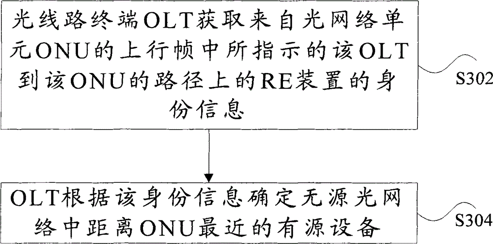
[0039] Step S302 may include the following steps:

[0040]Step S3022, the RE device writes its own identity information in the uplink frame;

[0041] Step S3024, the OLT receives the uplink frame and obtains the identity information.

[0042] In this method, the RE device writes its own identity information in the upstream frame, and the OLT determines the identity information of the active device closest to each ONU according to the content of the upstream frame carrying the RE identity information. This RE device automatic writing method can accurately and easily realize the carrying of the identity information of the RE device passed by the uplink frame, and does not need to set up a message to carry the information, which is simple to implement and has high efficiency.

[0043] The process for the RE device to write its own identity information in the uplink frame may include but not limited to the following two methods:

[0044] (1) Write the identity information into t...

Embodiment approach 2

[0063] Step S302 may include the following steps:

[0064] Step S3021, the RE device writes its own identity information in the downlink frame sent from the OLT to the ONU;

[0065] Step S3023, the ONU carries the identity information in the uplink frame and sends it to the OLT;

[0066] Step S3025, the OLT receives the uplink frame and obtains the identity information.

[0067] As another optional implementation, the RE device can write its own identity information in the downlink frame. After the ONU obtains the information, it writes it into the uplink frame and sends it to the OLT. The OLT carries the RE identity information according to the The content of the upstream frame determines the identity information of the active device closest to each ONU. This method can be used in combination with Embodiment 1.

[0068] The process for the RE device to write its own identity information in the downlink frame may include but not limited to the following two methods:

[006...

Embodiment 1

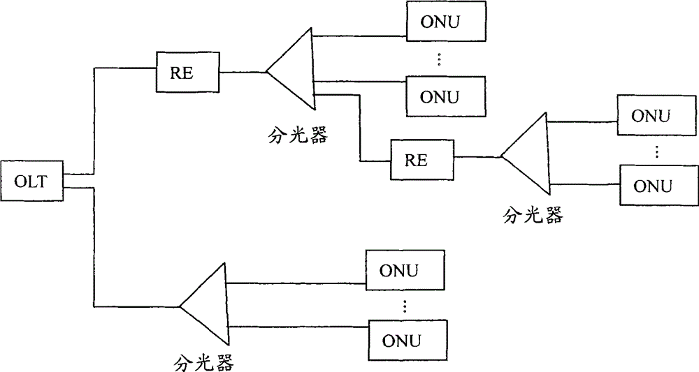
[0097] This embodiment describes in detail the method for the RE device to write its own identity information in the uplink frame, corresponding to the (1) method in the first embodiment above, the topology of the GPON system is as follows figure 2 As shown, the OLT writes its own identity information in the newly added field in the upstream frame through the RE device, and determines the identity information of the active device closest to each ONU in the GPON system.

[0098] In this embodiment, the uplink frame structure of a field carrying RE identity information (ie, RE identification (RE-ID)) is added as Figure 8 As shown, the RE-ID is located between the delimited domain and the bit interleaved parity (Bit Interleaved Parity, referred to as BIP) domain, and the RE-ID can also be located at any position between the delimited domain and the first DBRu domain , the RE-ID can also be located in the GEM frame header of the Gigabit PON Encapsulation Mode (GEM) frame in the ...


PUM


Abstract

The invention discloses a method and a system for determining a topology structure of a passive optical network (PON). The method comprises the following steps that: an optical line terminal (OLT) obtains identification information of a research entenders (RE) apparatus on a path from the OLT to an optical network unit (ONU), wherein the identification information is indicated in an uplink frame of the ONU; and the OLT determines active equipment nearest to the ONU in the PON according to the identification information, wherein the active equipment comprises an RE apparatus or an OLT. According to the invention, the OLT can manage the ONU conveniently.

Description

technical field [0001] The present invention relates to the communication field, in particular to a method and system for determining the topology of a passive optical network (Passive Optical Network, PON for short) system. Background technique [0002] The Gigabit-Capable Passive Optical Network (GPON for short) technology is an important technical branch of the PON, and is also a passive optical access technology using a point-to-multipoint topology. [0003] figure 1 It is a schematic diagram of the topology structure of the GPON system in the related art, such as figure 1 As shown, GPON is composed of an optical line terminal (Optical Line Terminal, OLT for short), an Optical Network Unit (ONU for short) at the user side, and an Optical Distribution Network (ODN for short). , usually using a point-to-multipoint network structure. Among them, the ODN is composed of passive optical devices such as single-mode optical fiber, optical splitter, and optical connector, and ...

Claims


Application Information

Patent Timeline
Patent Type & Authority Patents(China)
IPC IPC(8): H04L12/24H04B10/27H04Q11/00H04B10/25
Inventor 张伟良耿丹朱松林
Owner ZTE CORP
Why Eureka
Try Eureka