Supercharge Your Innovation With Domain-Expert AI Agents!

Brazing filler metal turbulent flow wave crest generator

A generator and wave crest technology, applied in the field of solder turbulence wave crest generators, can solve the problems of continuous welding and solder leakage, liquid flow disorder, product defect rate, repair rate, etc., and achieve lead-free welding with high quality and impact force. proper effect

Inactive Publication Date: 2011-10-19
WEIHAI SINOWILL ELECTRONICS EQUIP
View PDF4 Cites 0 Cited by
  • Summary
  • Abstract
  • Description
  • Claims
  • Application Information

AI Technical Summary

Problems solved by technology

There are many disadvantages in the solder wave crest generator mentioned above: one is the structure of the solder pump and the straight-through channel, which is not conducive to the formation of the impact potential energy of the solder wave peak, which is large and small; the second is that the solder pump outlet is not provided with solder The deflector, the liquid flow is disordered after the solder is discharged; the third is that there is no solder rectifier in the wave crest spout, resulting in the solder in the wave crest spout is still in a disordered state, which cannot effectively form an independent columnar protruding crest, and the wave crest is unstable
The above structure cannot guarantee the requirements of uniformity, continuity and appropriate impact force of the formed solder wave peak, which causes great instability to the lead-free soldering quality of printed circuit boards (hereinafter referred to as PCB), especially for tiny IC devices and The soldering of multi-pin IC devices is very easy to cause continuous soldering and missing soldering, and the product defect rate and repair rate are high, which is not conducive to improving the quality of PCB assembly, and then affects the quality and reliability of electronic products.

Method used


Image

  • Brazing filler metal turbulent flow wave crest generator
  • Brazing filler metal turbulent flow wave crest generator
  • Brazing filler metal turbulent flow wave crest generator

Examples


Embodiment Construction

[0019] The present invention will be further described below in conjunction with the accompanying drawings.

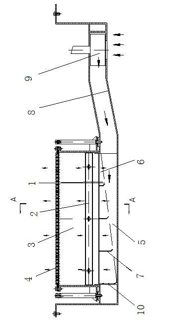
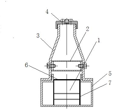
[0020] A solder turbulence wave crest generator is characterized in that it is composed of a deflector 1, a rectifier 2, a flow stabilizer 3 and a sprayer 4.

[0021] The deflector 1 in the present invention is made up of deflector groove 5, deflector net 6, deflector plate 7, deflector pipe 8 and centrifugal pump 9, and deflector groove 5 is provided with deflector net 6, deflector , 6 is a flat plate evenly distributed with round holes, the front end of the diversion groove 5 is provided with a baffle plate 10, the rear end of the diversion groove 5 is connected with the diversion pipe 8, and the other end of the diversion pipe 8 is provided with a centrifugal pump 9, The cross-section of the diversion groove 5 and the diversion pipe 8 is square, and a deflector 7 is arranged in the diversion groove 5, and the upper end of the diversion plate 7 is in contact with or ...


PUM


Abstract

The invention relates to a wave crest welder, in particular to a brazing filler metal turbulent flow wave crest generator; the brazing filler metal turbulent flow wave crest generator is characterized by consisting of a flow guiding device, a rectifier, a current stabilizer and a sprayer, wherein the flow guiding device consists of a flow guiding groove, a flow guiding net, a flow guiding plate, a flow guiding tube and a centrifugal pump; the rectifier consists of a rectifying cavity and a rectifying net; the current stabilizer is a current stabilizing cavity; the sprayer consists of a base and a nozzle. In the invention, the brazing filler metal is effectively settled and controlled in the operating process, so as to form uniform and continuous molten brazing filler metal with proper contact force, therefore, an independent bulged wave crest with a certain height of the molten brazing filler metal is formed, so as to be suitable for lead-free manufacture procedure of modern electronic products, realize high lead-free welding quality of PCB (printed circuit board), solve the prominent problems of affecting the lead-free welding process, and meet the requirements of the lead-free welding operation of the PCB.

Description

technical field [0001] The invention relates to a wave soldering machine, in detail, it is a solder turbulence wave generator which adapts to the lead-free process of modern electronic products and realizes high-quality lead-free soldering of PCBs. Background technique [0002] As we all know, lead is a poisonous substance. In order to protect the environment and promote human health, countries around the world have passed laws to prohibit the use of lead-containing solder in manufacturing industries such as electronics, automobiles and aircraft. With the development of my country's economy and the progress of society, the Chinese government has formulated relevant laws on the lead-free manufacturing of products. To solve the lead-free process of the electronic product manufacturing industry, it is necessary to solve the problem of lead-free solder, and the lead-free alloy solder has the following three disadvantages compared with lead (Sn-Pb) alloy solder. The welding temp...

Claims


Application Information

Patent Timeline
IPC IPC(8): H05K3/34
Inventor 任在旭王新宁尤建强付士政
Owner WEIHAI SINOWILL ELECTRONICS EQUIP
Features
  • R&D
  • Intellectual Property
  • Life Sciences
  • Materials
  • Tech Scout
  • Unparalleled Data Quality
  • Higher Quality Content
  • 60% Fewer Hallucinations
Learn More