Spiral lifting observation tower

A technology of spiral lifting and observation tower, which is applied in the direction of elevators, towers, public buildings, etc., can solve the problems of large mutual interference of tourists, poor viewing angle and comfort, poor staying feeling, and limited viewing angle, etc., to achieve climbing And the descending angle is gentle and comfortable

Inactive Publication Date: 2011-10-26
常强 +1
View PDF8 Cites 15 Cited by
  • Summary
  • Abstract
  • Description
  • Claims
  • Application Information

AI Technical Summary

Problems solved by technology

[0003] Among them, the viewing path of the high-altitude fixed cabin is fixed, tourists interfere with each other greatly, and the height does not change; the high-altitude rotating cabin can rotate horizontally, which is a common revolving restaurant; the height of the vertical sightseeing elevator changes, but the viewing angle and comfort and The feeling of staying is relatively poor; the viewing experience of the Ferris wheel is relatively good, and it is currently the most popular tourist attraction in the city, but the viewing angle is still limited; the sightseeing cableway needs to be combined with the natural terrain of mountains and valleys and the height is limited, and the viewing angle and height are limited

Method used


Image

  • Spiral lifting observation tower
  • Spiral lifting observation tower
  • Spiral lifting observation tower

Examples


Embodiment Construction

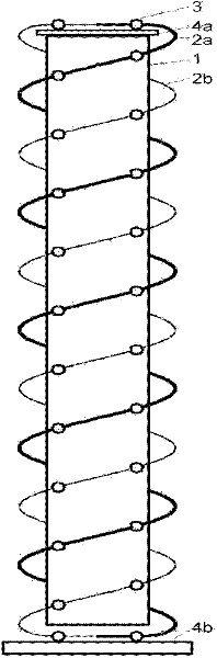
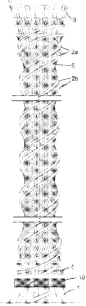
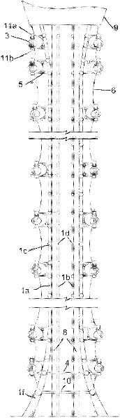
[0012] The observation tower of a kind of spiral lifting that the present invention proposes, such as figure 1 As shown, it includes an upright main structure 1, one or more pairs of spiral tracks 2 attached to the periphery of the main structure (only a pair of spiral tracks are shown in the figure), and each pair of spiral tracks 2 consists of an ascending track 2a and a descending track 2b Composition, the up track and the down track are connected end to end at both ends to realize the conversion of up and down; a plurality of mobile cabins 3 are arranged at intervals on the spiral track 2; wherein the mobile cabins on the up track 2a move upward along the track, The mobile cabin body on the down track 2b moves down along the track; it also includes the lower platform 4b (the upper platform 4a can also be added) arranged at the ends of the up track and the two ends of the down track, which is used for people to board and leave the cabin.

[0013] The specific embodiment of...


PUM


Abstract

The invention relates to a spiral lifting observation tower and belongs to the technical field of structures for observation in high-altitude sightseeing and entertainment or military, meteorology and other fields. The observation tower comprises a vertical main body structure, wherein a pair or more pairs of spiral tracks are attached on the periphery of the main body structure, each pair of the spiral tracks comprise an ascending track and a descending track, and the ascending tracks and the descending tracks are in head-tail connection at two ends, thus realizing conversion between ascending and descending; a plurality of mobile cabin bodies are arranged on the spiral tracks at intervals; the mobile cabin bodies on the ascending tracks move upward along the tracks, and the mobile cabin bodies on the descending tracks move downward along the tracks; and the spiral lifting observation tower further comprises getting-off platforms arranged at the head-tail connection conversion place of the ascending tracks and the descending tracks (getting-on platforms can also be additionally arranged) and used for enabling people to get on and get off the cabin bodies. The sightseeing angle changes incessantly and can basically realize 360-degree panoramic vision in different heights, and the ascending and descending angles are smooth and comfortable, thus the spiral lifting observation tower is widely suitable for various people groups.

Description

technical field [0001] The invention belongs to the technical field of observation structures in the fields of high-altitude viewing and amusement, military affairs, meteorology, etc., and particularly relates to the design of a spiral lifting observation tower. Background technique [0002] The existing non-aircraft aerial observation (or sightseeing) methods mainly include high-altitude fixed or rotating cabins (usually located in the middle or top of high towers), sightseeing elevators, Ferris wheels, and sightseeing cableways. [0003] Among them, the viewing path of the high-altitude fixed cabin is fixed, tourists interfere with each other greatly, and the height does not change; the high-altitude rotating cabin can rotate horizontally, which is a common revolving restaurant; the height of the vertical sightseeing elevator changes, but the viewing angle and comfort and The feeling of staying is relatively poor; the viewing experience of the Ferris wheel is relatively go...

Claims


Application Information

Patent Timeline
Patent Type & Authority Applications(China)
IPC IPC(8): E04H12/00E04H3/10B66B7/02B66B11/02
Inventor 常强高岩朵宁
Owner 常强
Why Eureka
Try Eureka