Small-power motor power testing apparatus with power loss-free and wide measuring range properties

A power testing, wide-range technology, applied in measuring devices, power metering, torque metering, etc., can solve the problems of unestimable measurement errors, increased motor testing costs, and inability to truly reflect the real parameter values ​​of the motor under test, reducing The effect of manufacturing precision

Active Publication Date: 2011-10-26
重庆麦田普偌科技有限公司
View PDF5 Cites 8 Cited by
  • Summary
  • Abstract
  • Description
  • Claims
  • Application Information

AI Technical Summary

Problems solved by technology

When the motor is outputting power, it must first overcome the inertia of the power absorber, so that the data of the torque sensor can be normal when the speed reaches a stable level. In the state of high speed, the loss caused by the coupling and high-speed rotating bearing cannot be measured. , especially in the case of testing tiny motors and high speeds, the measurement error cannot be estimated
Therefore, the accuracy of the traditional test method is poor, and it cannot truly reflect the real parameter value of the motor under test
At the same time, since the rotation speed and range of each power absorber cannot be changed, the traditional test method requires high manufacturing precision and sensitivity of the power absorber, which will inevitably lead to high cost of the power absorber, thus increasing the motor cost. cost of testing

Method used


Image

  • Small-power motor power testing apparatus with power loss-free and wide measuring range properties
  • Small-power motor power testing apparatus with power loss-free and wide measuring range properties

Examples


Embodiment 1

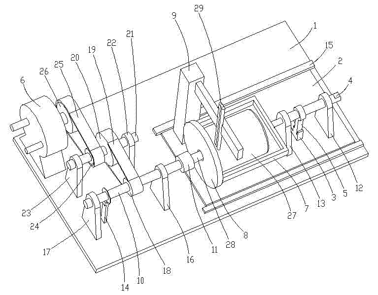
[0019] Such as figure 1 As shown, the base plate 1 is a rectangular flat plate structure, and two guide rails 15 are fixed on the surface of the front portion of the base plate 1 in a symmetrical manner. The two guide rails 15 are parallel, and a rectangular movable plate 2 is arranged between the two guide rails 15 , the sides of the movable plate 2 are slidably matched with the corresponding guide rails 15 . The movable plate 2 is guided by two guide rails 15, and can only slide relative to the base plate 1 in the front-rear direction. A semi-shaft 4 is arranged along the front-to-back direction above the front portion of the movable plate 2. The front portion of the semi-shaft 4 is supported by the first front support seat 12 through a bearing, and the rear portion of the semi-shaft 4 is connected with the second shaft through a bearing. The front support bases 13 are mutually supported, and the first and second front support bases 12, 13 are all fixed on the movable plate...

Embodiment 2

[0027] refer to figure 1 In this embodiment, there is no speed change mechanism, and the input shaft of the work absorber 6 is directly connected to the rear end of the power shaft 10 . The rest of the structure of this embodiment is the same as that of Embodiment 1, and will not be repeated here.

Embodiment 3

[0029] refer to figure 1 The speed change mechanism in this embodiment can also be replaced by a gear reduction box. The input shaft of the power absorber 6 is directly connected to the output shaft of the gear reduction box, and the rear end of the power shaft 10 is connected to the input shaft of the gear reduction box. The rest of the structure of this embodiment is the same as that of Embodiment 1, and will not be repeated here.


PUM


Abstract

The invention discloses a power testing apparatus for a small-power motor and the apparatus has power loss-free and wide measuring range properties. According to the invention, a front supporting seat is fixed on an active plate; a half axle is supported on the front supporting seat by a bearing; a moment rod is fixed on the axle body of the half axle; and a lower end of the moment rod is inserted into a testing position of a torque sensor. A rear end of the half axle and a center of a front end of a frame are fixed to each other; a rear end of the frame is fixed on an installation disk; a power shaft is arranged on the rear of the installation disk and is connected with a rear supporting seat through a bearing; the power shaft is connected with an input shaft of a dynamometer directly or by a speed change mechanism; and a rotating speed sensor is installed on the power shaft. According to the invention, a principle of a moment balance equation of Newton's third law is employed, wherein the equation is characterized in that sigma M is equal to an absolute value of-M, so that an equal corresponding relationship between a turning moment output by an output shaft of the motor and a counter turning moment that a housing of the motor is subjected to is obtained. And then the static counter torque, which is measured, is a torque output by the motor. The testing apparatus is free of losses and has a wide range; besides, an actual parameter value of the motor can be accurately tested by utilizing the testing apparatus.

Description

technical field [0001] The invention relates to a power testing device for a small motor with no loss and a wide range, which is used for power testing of high-speed brushless motors and small-power motors. Background technique [0002] At present, when motor manufacturers test the power of the motor, they always use the output shaft of the motor to directly connect with the power absorber. When the motor is outputting power, it must first overcome the inertia of the power absorber, so that the data of the torque sensor can be normal when the speed reaches a stable level. In the state of high speed, the loss caused by the coupling and high-speed rotating bearing cannot be measured. , especially in the case of testing tiny motors and high speeds, the measurement error cannot be estimated. Therefore, the accuracy of the traditional test method is poor, and it cannot truly reflect the real parameter value of the motor under test. At the same time, since the rotation speed and...

Claims


Application Information

Patent Timeline
Patent Type & Authority Applications(China)
IPC IPC(8): G01L3/24G01L3/22
Inventor 刘嘉华赖力
Owner 重庆麦田普偌科技有限公司
Why Eureka
Try Eureka