
Method for measuring rotating speed of main shaft of wind turbine generator system and mechanism for detecting rotating speed pulse

A spindle speed and measurement method technology, applied in the direction of linear/angular velocity measurement, velocity/acceleration/shock measurement, measuring device, etc., can solve the problems of unfavorable unit speed data acquisition accuracy and easy damage, and achieve strong anti-vibration and anti-vibration Disturbance characteristic, low cost of use, effect of smooth speed change value

Inactive Publication Date: 2011-10-26
RENERGY ELECTRIC TIANJIN
View PDF6 Cites 8 Cited by
  • Summary
  • Abstract
  • Description
  • Claims
  • Application Information

AI Technical Summary

Problems solved by technology

[0005] The present invention discloses a method for measuring the rotational speed of a main shaft of a wind turbine and its rotational speed pulse detection mechanism in order to solve the technical problems that the structure of the above-mentioned encoder for measuring rotational speed is easily damaged and unfavorable for the accuracy of unit rotational speed data acquisition.

Method used


Image

  • Method for measuring rotating speed of main shaft of wind turbine generator system and mechanism for detecting rotating speed pulse
  • Method for measuring rotating speed of main shaft of wind turbine generator system and mechanism for detecting rotating speed pulse
  • Method for measuring rotating speed of main shaft of wind turbine generator system and mechanism for detecting rotating speed pulse

Examples


Embodiment Construction

[0013] The present invention will be further described below in conjunction with the accompanying drawings and embodiments.

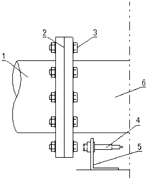
[0014] Such as figure 1 As shown, the flange plate 2 of the main shaft 1 of the wind power generating set connected to the hub mechanism 6 is provided with positioning bolts 3 at equal intervals, and the bracket 5 fixed on the nacelle or other positions supports a proximity switch 4, and the sensing head of the proximity switch is connected to the The end faces of the set bolts correspond. When the main shaft 1 rotates, adjust the distance between the sensor head of the proximity switch and the end face of the positioning bolt to obtain a relatively regular induction pulse signal. Usually, the distance between the sensor head of the proximity switch and the end face of the positioning bolt is 10-15mm. The pulse output signal of the proximity switch is connected to the high-speed counting module.

[0015] Since the number of positioning bolts is fixed,...


PUM


Abstract

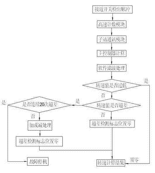
The invention provides a method for measuring the rotating speed of the main shaft of a wind turbine generator system and a mechanism for detecting the rotating speed pulse. A high speed counting module acquires the pulse signal of the main shaft rotating for a circle. A main controller calculates the rotating speed value when the main shaft rotates for a circle under the condition of each pulse period time and carries out software filtering processing. The software filtering processing is filtering too low rotating speed values and setting the rotating speed maximal change value when the main shaft rotates for a circle including acceleration and deceleration. The rotating speed maximal change value is compared with the difference of the rotating speed values corresponding to the present and the last pulse period. If the difference is larger than the rotating speed maximal change value, the present rotating value is invalid. The main controller processes the present rotating value to make it become a valid rotating value, thereby overcoming the influence from interferences such as vibrations and the like on the rotating value of the main shaft. According to the invention, a smooth rotating speed change value can be obtained. The invention has strong anti-vibration and noiseproof features, the use cost is lower than that of an increment type encoder and the invention is characterized by simple installation and good measuring precision.

Description

technical field [0001] The invention belongs to wind power generation equipment, and in particular relates to a method for measuring the rotational speed of a main shaft of a wind turbine and a detection mechanism for a rotational speed pulse. Background technique [0002] In the operation of wind turbines, especially in the control of pitch and excitation, the speed of the main shaft of the wind turbine is the necessary basic calculation data, and the accuracy of data acquisition is also very important. [0003] In existing wind turbines, it is a conventional speed measurement method to use an encoder to measure the rotational speed. Its basic structure is to lead out a speed measurement shaft in the gearbox, and install an incremental encoder on this shaft. [0004] The structure of the above-mentioned encoder measuring the rotational speed has the following defects: the encoder is not only easily damaged but also detrimental to the accuracy of the data acquisition of the ...

Claims


Application Information

Patent Timeline
IPC IPC(8): G01P3/481
Inventor 刘博赵涛郭小叶
Owner RENERGY ELECTRIC TIANJIN
Learn More