Rotary anti-winding device

A technology of anti-winding and rotating shaft, which is applied in the installation of cables, the arrangement of cables between relative moving parts, and electrical components, etc. It can solve the problems of complicated connection lines, improve reliability, reduce complexity, and reduce the number of wires Effect

Inactive Publication Date: 2011-10-26
SHANGHAI NORMAL UNIVERSITY
View PDF3 Cites 5 Cited by
  • Summary
  • Abstract
  • Description
  • Claims
  • Application Information

AI Technical Summary

Problems solved by technology

The controller of the robot is installed on the body of the robot, and the roller motor at the end of the cross-shaped bracket is installed at the end of the bracket. The connection lines of the 16 roller motors are relatively complicated, and one end of the signal line is moving. If there is no special device When the two ends of the signal line are connected, winding will occur. Therefore, it is urgent to provide an anti-winding device to solve the above problems

Method used


Image

  • Rotary anti-winding device
  • Rotary anti-winding device
  • Rotary anti-winding device

Examples


Embodiment example

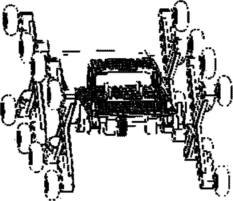
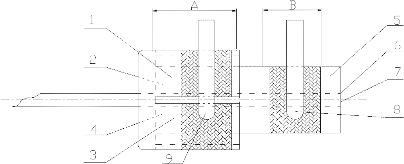
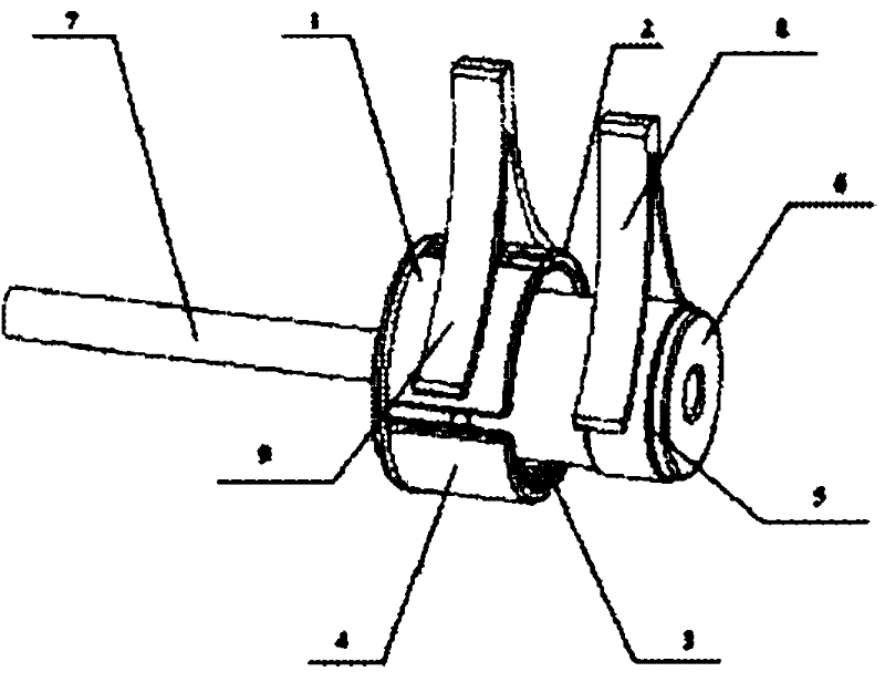
[0034] Taking the application of the anti-winding device in the cross-shaped wheel train obstacle-crossing robot as an example, the installation of this device in the robot is consistent with the description in the specific implementation. During the wiring process, because the contact surface of the anti-winding device and the shrapnel is facing upward, if image 3 shown. And the cross-shaped crossing wheel train needs signal-driven wheels that must be in contact with the ground, that is, downward, such as Figure 4 shown. The outer ring of the anti-winding device is divided into four parts 1, 2, 3 and 4, and the four ends of the cross-shaped spanning wheel train are also divided into corresponding four parts 1', 2', 3' and 4'. The connection of the line is 1 to 4', 2 to 3', to ensure that when the 1 and 2 conductive coils of the outer ring A of the anti-winding device are in contact with the shrapnel, the cruciform crosses the 3', 3', and The 4' rollers are powered on. T...


PUM


Abstract

The invention relates to the transmission field of mechanical electrical equipment and provides a rotary anti-winding device. The rotary anti-winding device comprises a spindle (7) arranged on a rack in a penetrating mode and N idler wheels (15), wherein the N idler wheels (15) are arranged at the periphery of the spindle (7) and driven by N idler wheel motors (13) respectively; a shaft sleeve A and a shaft sleeve B are coaxially fixed on the spindle (7) in an insulated mode and a section of conductive coil (5) is wound on the shaft sleeve A or the shaft sleeve B and the shaft sleeve A or theshaft sleeve B is connected with one pole of each power line of the N idler wheel motors (13) respectively; N sections of conductive coils are wound on the other shaft sleeve uniformly at intervals in a periphery direction; the N sections of conductive coils are connected with the other pole of each power line of the N idler motors (13) respectively; and two V-shaped clamping conductive clips (8 and 9) clamp and contact with one section of conductive coil or the N sections of conductive coils respectively and are connected with two electrodes of a power supply respectively. The rotary anti-winding device is simple in structure, decreases the number of transmission wires of an idler wheel motor of a robot, improves the reliability of the robot in the operation process, reduces the use costof the robot and ensures the complicated signal transmission of the robot.

Description

technical field [0001] The invention relates to the field of mechanical and electrical transmission, in particular to a device structure in which electric wires are transmitted to a rotatable mechanism without winding. Background technique [0002] With the improvement of the level of industrialization, various complex mechanical structures are more and more widely used in various fields, and the requirements for signal transmission of mechanical equipment are also becoming more and more complex. There are two ways of signal transmission: wired transmission and wireless transmission. Wired transmission can be divided into two types: wired direct transmission and wired indirect transmission. Wired direct transmission is a method of direct connection and transmission through corresponding signal transmission lines; wired indirect transmission is transmission between two parts in relative motion through special methods, such as relative sliding and relative rotation. The spec...

Claims


Application Information

Patent Timeline
Patent Type & Authority Applications(China)
IPC IPC(8): H02G11/00
Inventor 王丽慧陈志红赵建军谭化宏吴鹏飞严昊宇戴莉
Owner SHANGHAI NORMAL UNIVERSITY
Why Eureka
Try Eureka