Portable closestool

A toilet, portable technology, applied to household appliances, resistance to vector-borne diseases, sanitary equipment and other directions, can solve the problems of inconvenience, cannot be folded for use, takes up a large space, etc., and achieves the effect of being easy to carry

Inactive Publication Date: 2011-11-02
NINGBO CHENGBANG OFFICE AUTOMATION TECH
View PDF10 Cites 8 Cited by
  • Summary
  • Abstract
  • Description
  • Claims
  • Application Information

AI Technical Summary

Problems solved by technology

[0002] Portable toilets currently on the market are often not foldable and take up a lot of space when carried
The inflatable p

Method used


Image

  • Portable closestool
  • Portable closestool
  • Portable closestool

Examples


Embodiment 1

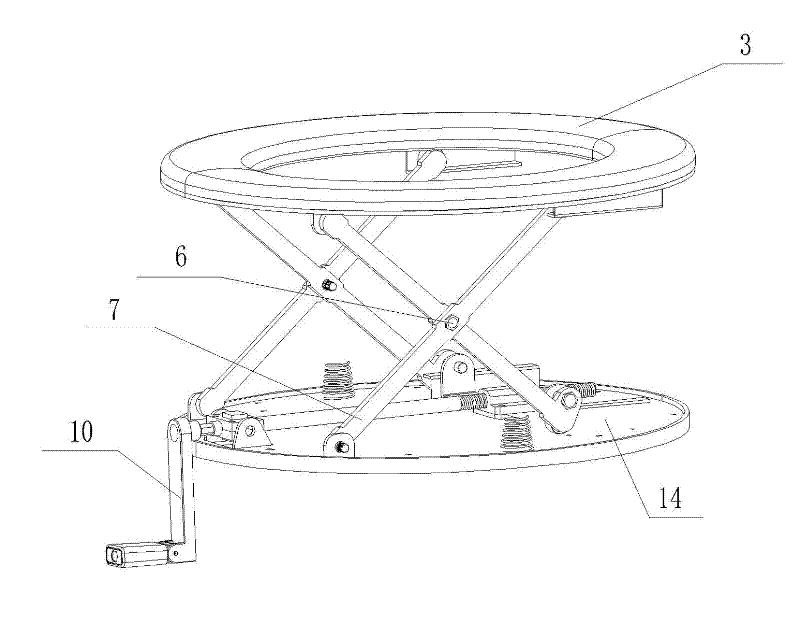
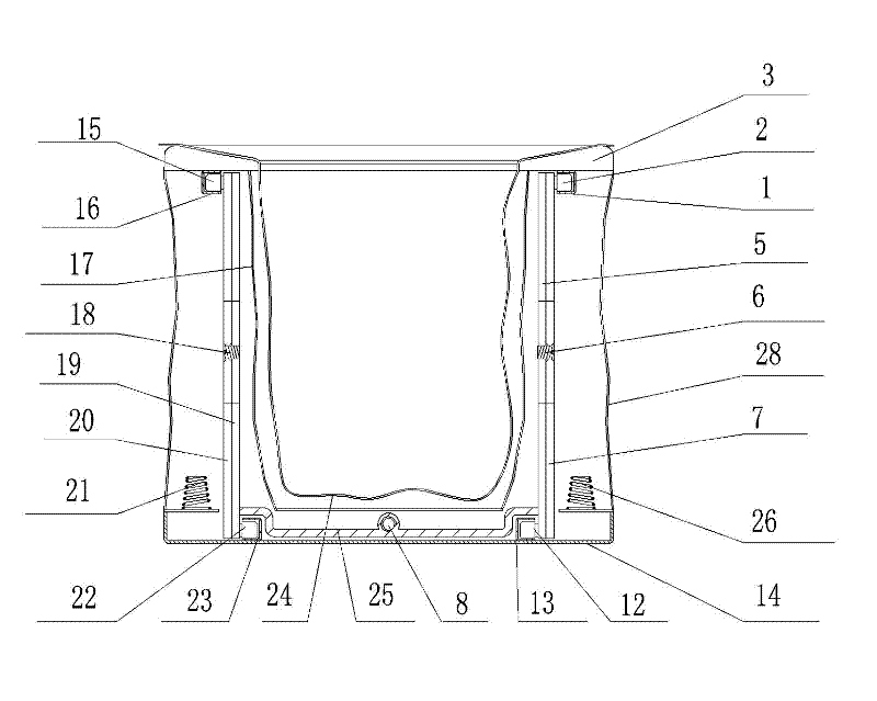
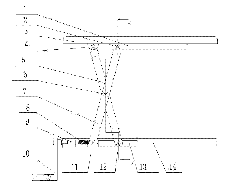
[0040] Refer to attached Figure 1-6 . This embodiment includes upper right guide rail 1, upper right pulley 2, top plate 3, upper right sliding hinge 4, right strut A5, right strut hinge 6, right strut B7, screw shaft 8, front screw shaft seat 9, hand crank 10 , right lower sliding hinge 11, right lower pulley 12, right lower guide rail 13, bottom plate 14, left upper pulley 15, left upper guide rail 16, inner retaining cloth 17, left strut hinge 18, left strut A19, left strut B20, left Support spring 21, left lower pulley 22, left lower guide rail 23, waste bag 24, connecting rod 25, right support spring 26, portable bag 27, outer retaining cloth 28.

[0041] Described support mechanism comprises the support bar that is arranged at the bottom of top plate 3 symmetry intersects, is the left strut A19 that crosses each other, left strut B20 and the right strut A5 that intersects each other, right strut B7 respectively, and described left strut A19 and the left strut B20 are ...

Embodiment 2

[0052] Refer to attached Figure 7~11 , the present embodiment includes hinge A31, hook 32, top plate 3, hinge B34, hinge pin B35, upper support plate 36, torsion spring 37, hinge pin D38, lower support plate 39, hinge pin C310, hinge C311, bottom plate 14, Waste bag 24, carrying bag 27, hook spring 315, hinge pin 316, hook stopper 317.

[0053]In this embodiment, the support mechanism includes an upper support plate 36 and a lower support plate 39, the upper support plate 36 is connected with the top plate 3 through a hinge B34, the hinge B34 is fixed on the top plate 3, and the upper support plate 36 is connected through a hinge pin B35 Connected on the hinge B34, the lower end of the upper support plate 36 and the upper end of the lower support plate 39 are connected through a hinge; the limiting device includes: a torsion spring is provided at the contact of the upper support plate 36 and the lower support plate 39 37. When the torsion spring 37 opens between the upper su...

Embodiment 3

[0065] Refer to attached Figure 13~16 , including: top plate 3, strut 51, strut joint A52, strut joint B53, bottom plate 14, connecting rod A54, connecting rod B55, rotary disc 56, rotary disc shaft 57, limit column A58, limit Column B59, handle 510, bearing A511, pivot pin A512, pivot pin B513, bearing B514, pivot pin C515.

[0066] In this embodiment, the support mechanism includes: a rotatable rotating disk 56 is provided on the bottom plate 14, at least three pole connectors A52 are provided under the top plate 3, and the same number of The strut joint B53, the strut joint A52 and the strut joint B53 are connected by a strut 51, the top plate 3 can rotate, and the strut joint B53 can rotate on the bottom plate 14, so The brace connector B53 is connected to the connecting rod B55, the connecting rod B55 is connected to the connecting rod A54, the connecting rod A54 is connected to the rotating disk 56, and the limiting device is arranged on the bottom plate 14.

[0067] ...


PUM


Abstract

The invention discloses a portable closestool. The special structure is used on occasions such as outdoors, hospital wards, internal spaces of automobiles and the like where indoor toilets are in short supply or people cannot go to toilets conveniently, and is convenient to carry. The portable closestool comprises a top plate (3), wherein a supporting mechanism which can extend and retract along upward and downward directions is arranged below the top plate (3); and a limiting device which is used for fixation during extension and retraction is arranged on the supporting mechanism. A bottom plate (14) can be alternatively arranged below the supporting mechanism, and the supporting mechanism can be connected with the bottom plate (14). The top plate (3) can be a ring of which the middle part is provided with holes. When the portable closestool is used, the supporting mechanism below the top plate (3) is unfolded along upward and downward directions, fixed by the limiting device, and sleeved with a refuse bag; after the portable closestool is used, the refuse bag is removed, and the supporting mechanism is folded; and the portable closestool is convenient to carry and can be repeatedly used.

Description

technical field [0001] The present invention relates to toilets. Background technique [0002] Portable toilets on the market are often not foldable and take up a lot of space when carried. The inflatable portable toilet is inconvenient because it is troublesome to inflate, and the supporting force is not enough when used. Contents of the invention [0003] The technical problem to be solved by the present invention is to provide a portable toilet which is convenient to fold, carry and use. [0004] In order to solve the problems of the technologies described above, the present invention adopts the following technical solutions: [0005] The toilet includes a top plate 3 , a supporting mechanism capable of stretching in the up and down direction is provided under the top plate 3 , and a limiting device for fixing when stretching is arranged on the supporting mechanism. [0006] Compared with the prior art, the present invention has the following advantages: when the pre...

Claims


Application Information

Patent Timeline
IPC IPC(8): A47K11/02A47K11/04
CPCA47K11/02Y02A50/30A47K11/00
Inventor 沈金龙刘涌飞
Owner NINGBO CHENGBANG OFFICE AUTOMATION TECH
Why Eureka
Try Eureka