Bearing dismounting device

A bearing dismounting device and splint technology, which is applied to hand-held tools, manufacturing tools, etc., can solve the problems of poor versatility of the expansion puller, easy to pull off the inner ring of the bearing, damage to the bearing, etc. Accuracy and service life, the effect of easy assembly

Inactive Publication Date: 2011-11-02
力帆科技(集团)股份有限公司
View PDF5 Cites 15 Cited by
  • Summary
  • Abstract
  • Description
  • Claims
  • Application Information

AI Technical Summary

Problems solved by technology

Since the inner ring and the outer ring of the bearing only have a small groove, which are connected by multiple steel balls, the method of expansion and drawing is not only laborious, but also easily pulls off the inner ring of the bearing, resulting in damage to the bearing.
In addition, the universality of the expansion puller is not strong, bearings of different sizes need to be equipped with different types of pullers, and the cost is high

Method used


Image

  • Bearing dismounting device
  • Bearing dismounting device
  • Bearing dismounting device

Examples


Embodiment 1

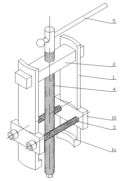
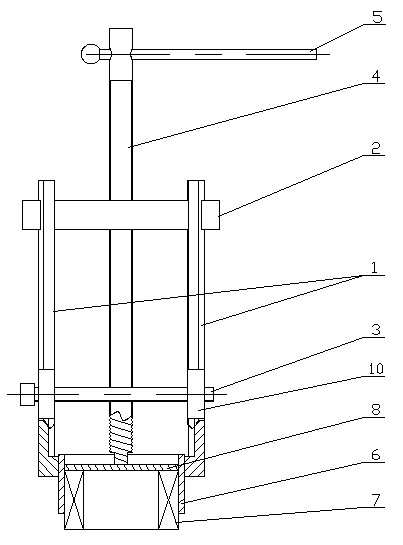
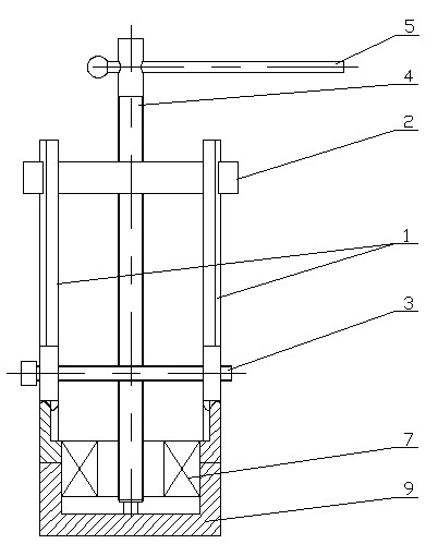
[0019] Such as figure 1 As shown, the present invention is made of parts such as splint 1, beam 2, fastener 3, push rod 4, rocker arm 5 and positioning block 10, and two splints 1 are arranged in the mode of left and right symmetry, and the upper end of these two splints 1 It is fixedly connected by the same crossbeam 2 that passes through. A clamping boss 1a is integrally formed on the opposite surfaces of the lower ends of the two splints 1. The opposite surfaces of the clamping bosses 1a at the lower ends of the two splints 1 are circular arc surfaces, and the left and right two clamping bosses 1a The arc faces are on the same circumference.

[0020] from figure 1 It can be seen from the figure that positioning blocks 10 are fixedly worn on the lower parts of the two splints 1, the positioning blocks 10 on the left and right sides are symmetrically distributed, and fasteners 3 are connected between the positioning blocks 10 on the left and right sides. Part 3 is preferab...

Embodiment 2

[0026] refer to figure 1 , In this embodiment, the upper ends of the two splints 1 and the beam 2 are connected by an adjustable structure. For example, the upper end of splint 1 is looped on beam 2 and positioned by screws. In this way, by adjusting the positions of the two splints 1 on the beam 2, the distance between the two clamping bosses 1a can be adjusted to meet the needs of dismounting bearings of different specifications. The rest of the structure of this embodiment is the same as that of Embodiment 1, and will not be repeated here.


PUM


Abstract

The invention discloses a bearing dismounting device. The upper end of each of two clamping plates (1) is fixed through a transverse beam (2); the opposite surfaces of the lower ends of the two clamping plates are provided with clamping bosses (1a); a fastening piece (3) is connected between the lower parts of the two clamping plates (1); a pushing rod (4) is arranged between the two clamping plates (1); the pushing rod (4) is in parallel to the clamping plates (1), and the distances from the pushing rod to the clamping plates (1) are equal; and the pushing rod (4) penetrates through the middle part of the transverse beam (2) from top to bottom, and the pushing rod (4) and the transverse beam (2) are in threaded fit. The bearing dismounting device provided by the invention has the advantages of simple structure, low cost, light weight and high generality, is easy to assembly, is not restricted by the area, not only is convenient and reliable to operate and move, but also can be used for effectively improving the bearing dismounting efficiency and simultaneously avoiding the abrasion between the bearing and an outer sleeve.

Description

technical field [0001] The invention relates to a bearing dismantling device, which is used for dismantling bearings in industries such as automobile, motorcycle and electromechanical industries. Background technique [0002] Bearings are important parts for relative rotation between components in industries such as automobiles, motorcycles, and electromechanical industries. When performing maintenance, it is often necessary to disassemble the bearing from the specific bearing housing. The traditional disassembly method is to strike with iron rods and hammers. In order to prevent the bearing from being damaged, it is usually necessary to add a thick wooden board to the end surface of the bearing. This method of knocking and dismounting is not only labor-intensive and inefficient, but also easily knocks the bearing and causes damage due to uneven force. At the same time, knocking increases the internal stress of the bearing and the outer casing, which will affect its accura...

Claims


Application Information

Patent Timeline
Patent Type & Authority Applications(China)
IPC IPC(8): B25B27/02
Inventor 赵正东
Owner 力帆科技(集团)股份有限公司
Why Eureka
Try Eureka