Belt conveyor sweeper

A technology for belt conveyors and cleaners, which is applied in the direction of conveyor objects, cleaning devices, transportation and packaging, etc. It can solve problems such as inconvenient installation, maintenance and replacement, unstable operation of cleaners, and deformation of scrapers of cleaners. Achieve the effect of stable and reliable fixing method, easy cleaning of adhered materials, and stable contact

Inactive Publication Date: 2011-11-02
CHENGDU DAHONGLI MACHINERY
View PDF6 Cites 21 Cited by
  • Summary
  • Abstract
  • Description
  • Claims
  • Application Information

AI Technical Summary

Problems solved by technology

After these cleaners have been used for a period of time, the scraper blades of the cleaners are often deformed and worn, which leads to unstable operation of the cleaners. It is necessary to manually adjust the upper and lower distances of the cleaners manually at intervals to make the scraper blades of the cleaners and the conveyor belt The contact area reaches ≥75% of the normal use requirement
In addition, users need to adjust many parts of the existing cleaner during the maintenance process. Because the belt conveyor is a lifting transport machine, the installation position is relatively high. and take appropriate safety precautions to prevent accidents
[0004] Existing cleaner scrapers have various shapes, all of which are in direct contact with the belt surface, usually in a vertical contact mode. Inconvenient to install, maintain and replace
The contact force between the scraper and the belt surface is also very important. There are many ways to adjust the contact force. Some use spring adjustment, and some use weight levers. However, the mechanism is complicated and cannot cooperate well with the scraper, which also affects the cleaner. usage of

Method used


Image

  • Belt conveyor sweeper
  • Belt conveyor sweeper
  • Belt conveyor sweeper

Examples


Embodiment Construction

[0038] The present invention will be further described below in conjunction with the specific embodiments and accompanying drawings. The specific embodiments and accompanying drawings are further descriptions of the principles of the present invention, and do not limit the present invention in any way. The same or similar technologies as the present invention do not exceed the protection scope of the present invention. .

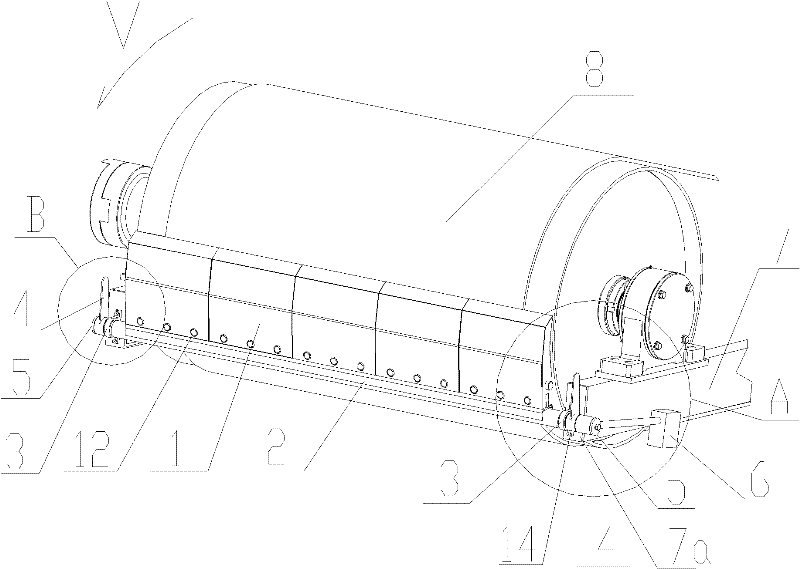
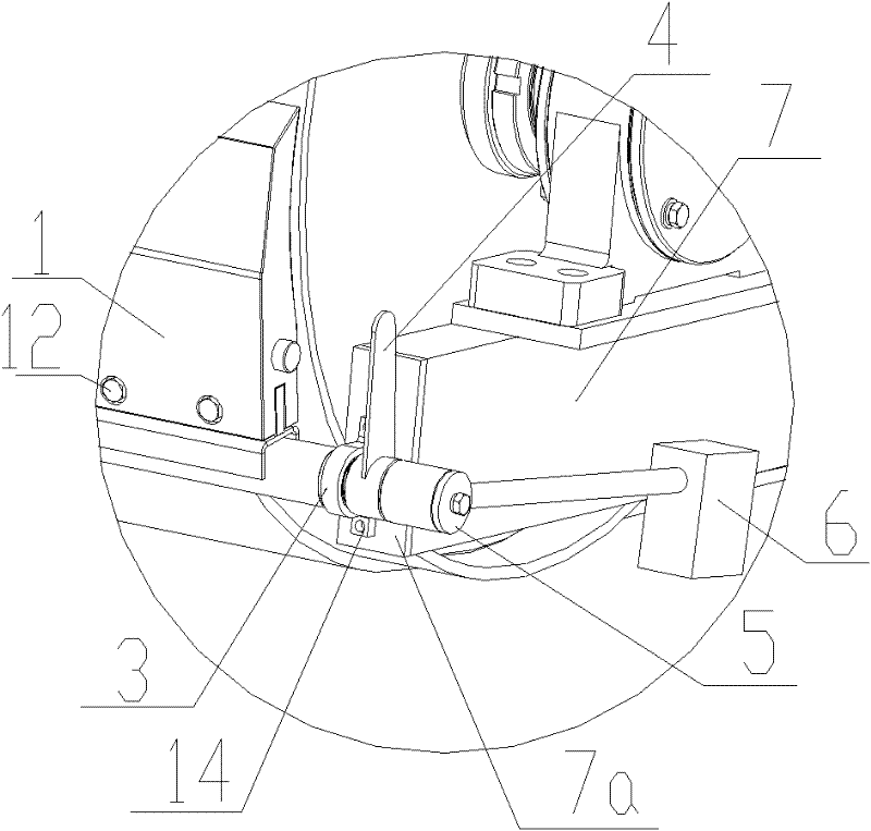
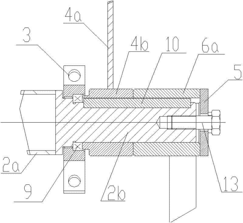
[0039] Belt conveyor cleaner, including scraper, scraper connection mechanism and scraper adjustment mechanism, scraper 1 is set along the arc surface of the belt, scraper 1 has an arc 1e matching with the arc surface of the belt, scraper 1 end 1f Contact with the belt; the scraper connecting mechanism has a shaft 2, the scraper 1 is axially connected and fixed along the shaft 2, and the two ends of the shaft 2 are hinged with the side beam 7 of the belt conveyor; the scraper adjustment mechanism has a lever 6b, and one end of the lever 6b has a matching The...


PUM


Abstract

The invention discloses a belt conveyor sweeper, which comprises scrapers, a scraper connecting mechanism and a scraper adjusting mechanism, wherein the scrapers are arranged along a belt arc surface and have an arc shape matched with the belt arc surface; the end parts of the scrapers are contacted with a belt; the scraper connecting mechanism is provided with a shaft; the scrapers are axially and fixedly connected along the shaft; two ends of the shaft are hinged with a side beam of a belt conveyor; the scraper adjusting mechanism is provided with a lever; and one end of the lever is provided with a counterweight block, and the other end of the lever is fixedly connected with the shaft. The belt conveyor sweeper has a sweeper scraper structure which is better matched with the conveyor belt; a fixing mode is more stable and reliable; in a sweeper adjusting device, due to the adoption of a gravity adjusting device, contact force between the scrapers and the belt can be adjusted in multiple directions through torque generated by the shaft, so that the defect of vertical contact force between the scrapers and the surface of the belt is overcome, the protection of the belt is facilitated, and the counterweight block can be adjusted in an addition and subtraction mode; and the belt conveyor sweeper has higher sweeping capacity, a more optimized structure and low manufacturing cost and is convenient to mount, maintain and replace.

Description

technical field [0001] The invention belongs to the field of belt conveyor manufacturing, in particular to the field of design and manufacture of conveyor belt cleaners in belt conveyors. Background technique [0002] The function of the cleaner is to remove the adhered material on the conveyor belt and accumulate these materials in the discharge area. If the material adhering to the conveyor belt is not cleaned cleanly and falls when passing the return roller, a large amount of material will accumulate soon, and even contact the return conveyor belt to cause a downtime accident. At the same time, the material is brought to the return section, which may cause strong wear on the conveyor belt, and form fouling on the lower idler roller, causing the conveyor belt to deviate. The requirements that an ideal cleaner should meet are: work on the lower part of the unloading drum so that the cleaned material can be sent directly into the unloading chute; it does not affect the norm...

Claims


Application Information

Patent Timeline
Patent Type & Authority Applications(China)
IPC IPC(8): B65G45/14
Inventor 甘泽全李松杨金秀
Owner CHENGDU DAHONGLI MACHINERY
Why Eureka
Try Eureka