Switching power circuit for three-phase intelligent electric energy meter

A technology of switching power supply circuit and smart energy meter, which is applied in the direction of electrical components, output power conversion device, irreversible AC power input conversion to DC power output, etc., can solve low-level problems, and achieve simple and reliable, strong cost Advantages and Effects of Practical Value

Active Publication Date: 2011-11-09
JIANGSU LINYANG ENERGY CO LTD
View PDF10 Cites 5 Cited by
  • Summary
  • Abstract
  • Description
  • Claims
  • Application Information

AI Technical Summary

Problems solved by technology

[0006] (4) Competitive cost: the cost of switching power supply must not be higher than the cost of existing linear power supply
[0007] Chinese patent CN201811993 "Three-phase four-wire low-power switching power supply watt-hour meter", Chinese patent CN1410856A "electronic circuit device with harmonic suppression and voltage stabilization function and its control method" and Chinese patent CN101533082A "half-wave rectification of an electric energy meter "Circuit" and other patents and documents partially propose a variety of solutions from different angles, but these solutions cannot completely solve the above problems, which is the main reason why switching power supplies have not been promoted in my country's electric energy meter industry so far.

Method used


Image

  • Switching power circuit for three-phase intelligent electric energy meter
  • Switching power circuit for three-phase intelligent electric energy meter
  • Switching power circuit for three-phase intelligent electric energy meter

Examples


Embodiment Construction

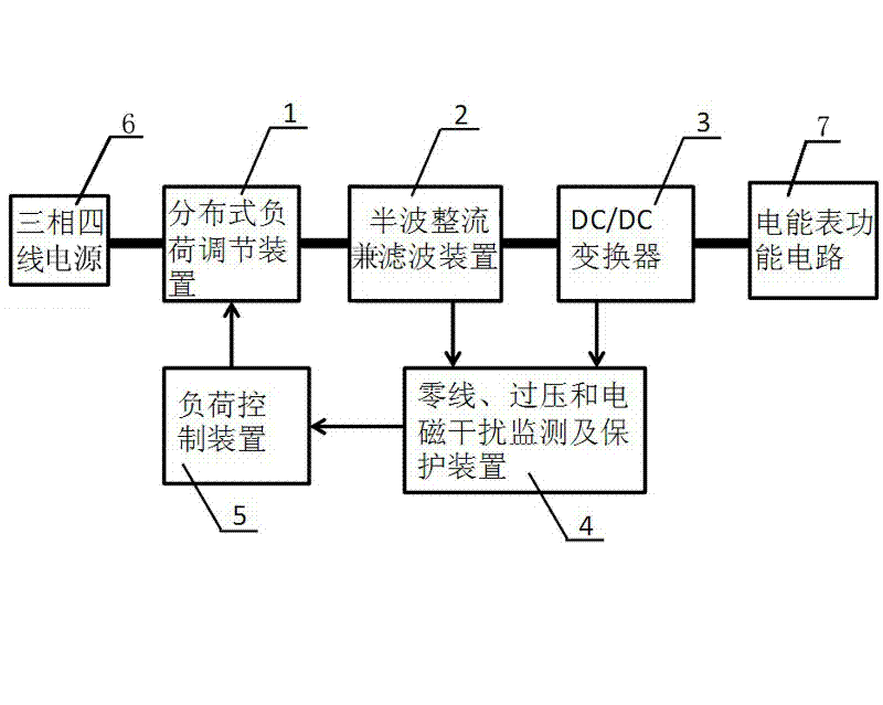
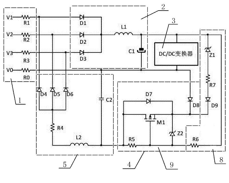
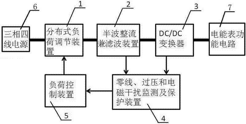
[0021] Such as figure 1 with 2 As shown, a switching power supply circuit for a three-phase smart energy meter of the present invention includes a distributed load regulating device 1, a half-wave rectification and filtering device 2, a neutral line, overvoltage and electromagnetic interference monitoring and protection device 4, and The load control device 5, the distributed load regulating device 1 is powered by the three-phase four-wire power supply 6, the distributed load regulating device 1 is connected to one end of the half-wave rectifying and filtering device 2, and the other end of the half-wave rectifying and filtering device 2 outputs to the DC / DC converter 3, DC / DC converter 3 is connected with electric energy meter functional circuit 7, one end of neutral line, overvoltage and electromagnetic interference monitoring and protection device 4 is connected with half-wave rectification and filtering device 2 and DC / DC converter 3, The other end of the neutral line, o...


PUM


Abstract

The invention discloses a switching power circuit for a three-phase intelligent electric energy meter. The switching power circuit comprises a distributed load regulation device (1), a half-wave rectification and filtration device (2), a zero-line, over-voltage and electromagnetic interference monitoring and protection device (4) and a load control device (5), wherein the distributed load regulation device (1) is supplied with power by a three-phase four-wire power supply (6); the distributed load regulation device (1) is connected with one end of the half-wave rectification and filtration device (2); the other end of the half-wave rectification and filtration device (2) is output to a direct current (DC) / DC converter (3); the DC/DC converter (3) is connected with an electric energy meter functional circuit (7); one end of the zero-line, over-voltage and electromagnetic interference monitoring and protection device (4) is connected with the half-wave rectification and filtration device (2) and the DC/DC converter (3); the other end of the zero-line, over-voltage and electromagnetic interference monitoring and protection device (4) is connected with one end of the load control device (5); and the other end of the load control device (5) is connected with the distributed load regulation device (1). The switching power circuit for the three-phase intelligent electric energy meter has the advantages of low cost, high reliability and effective restraint capacity of strong electromagnetic interference and pole-end harmonic current interference.

Description

technical field [0001] The invention relates to a switching power supply circuit for a three-phase intelligent electric energy meter, which belongs to the technical field of electronic electric energy meters. Background technique [0002] At present, most electric energy meters in our country use a linear rectifier power supply based on a power frequency transformer to supply power to the inside of the meter. The efficiency of this power supply is very low, usually only 30% to 40%. With the intelligent innovation of electric energy meters, the power consumption of electric energy meters has also increased significantly. For example, the power consumption of three-phase meters has increased from less than one watt to several watts. In other words, the increase in the overall power consumption of the electric energy meter will be very surprising; on the other hand, the switching power supply technology uses power semiconductor devices to control the conversion of energy quickl...

Claims


Application Information

Patent Timeline
Patent Type & Authority Applications(China)
IPC IPC(8): H02M7/06H02M1/32
Inventor 朱德省徐文辉张磊杨金土
Owner JIANGSU LINYANG ENERGY CO LTD
Why Eureka
Try Eureka