
Hydraulic crushing bucket

A technology of hydraulic crushing and hydraulic motor, applied in the direction of earthmoving machine/shovel, construction, etc., can solve the problems of high price of large-scale crushing equipment, inability to perform crushing work, and difficulty in fixing the installation position, so as to achieve convenient, fast and convenient installation. The effect of replacing and reducing maintenance costs

Pending Publication Date: 2018-08-17
南阳红阳远大重工有限公司
View PDF5 Cites 5 Cited by
  • Summary
  • Abstract
  • Description
  • Claims
  • Application Information

AI Technical Summary

Problems solved by technology

Although the ability to process materials per unit time is strong, there are the following disadvantages: 1. The equipment is large in size, heavy in weight, high in power, difficult to fix the installation position and difficult to move; 2. Most of the crushing equipment on the market realizes the crushing function through belt transmission. Small crushing force; 3. In some special occasions such as limited space and narrow and uneven roads, large-scale crushing equipment cannot enter, and the crushing work cannot be carried out; 4. In addition, short-term crushing of stones and buildings is required in urban reconstruction, road reconstruction, etc. For occasions such as waste, due to the short construction period and frequent transfer of construction sites, large-scale fixed crushing equipment is no longer suitable for such a working environment; 5. This large-scale crushing equipment is expensive and expensive

Method used


Image

  • Hydraulic crushing bucket
  • Hydraulic crushing bucket
  • Hydraulic crushing bucket

Examples


Embodiment Construction

[0013] The following will be described in detail in conjunction with the technical solutions in the embodiments of the present invention:

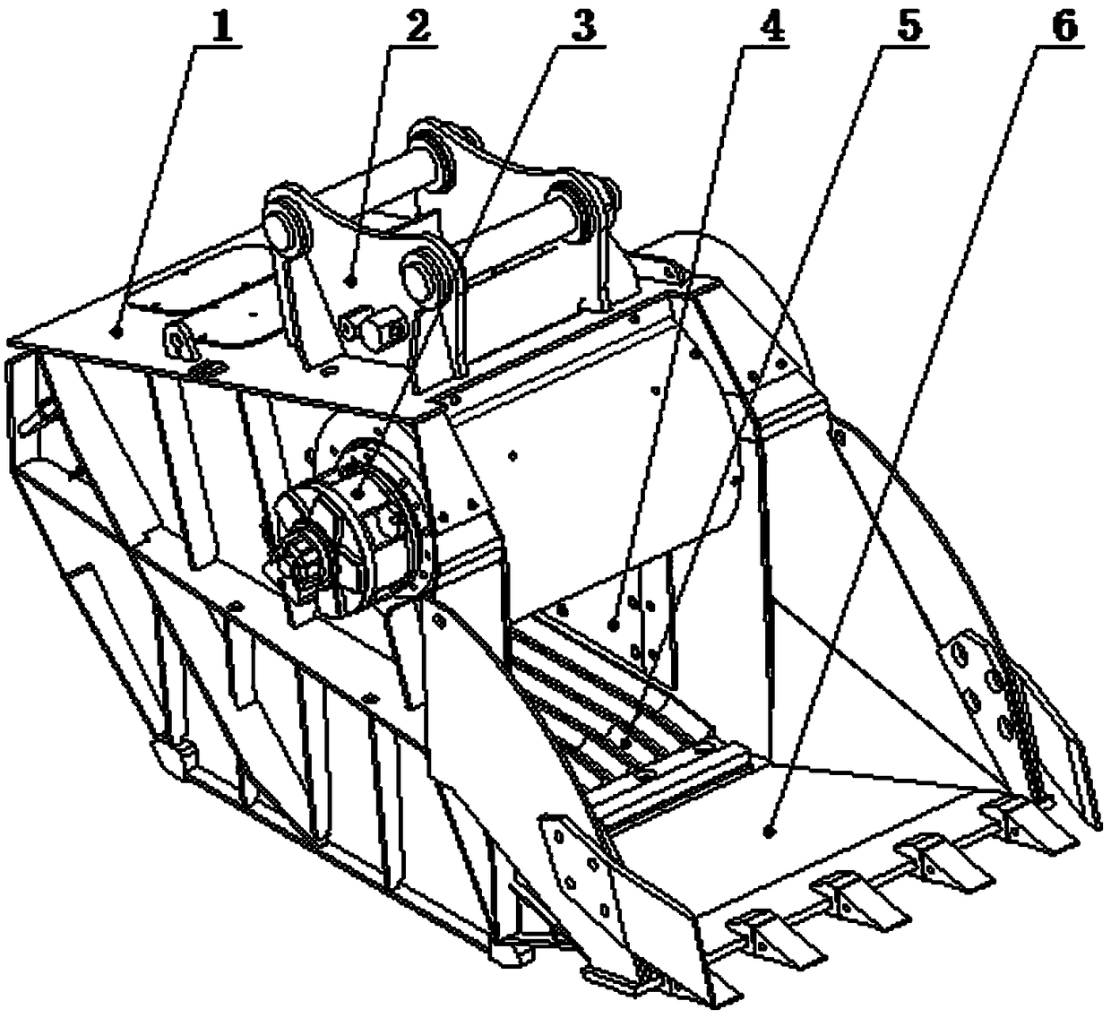
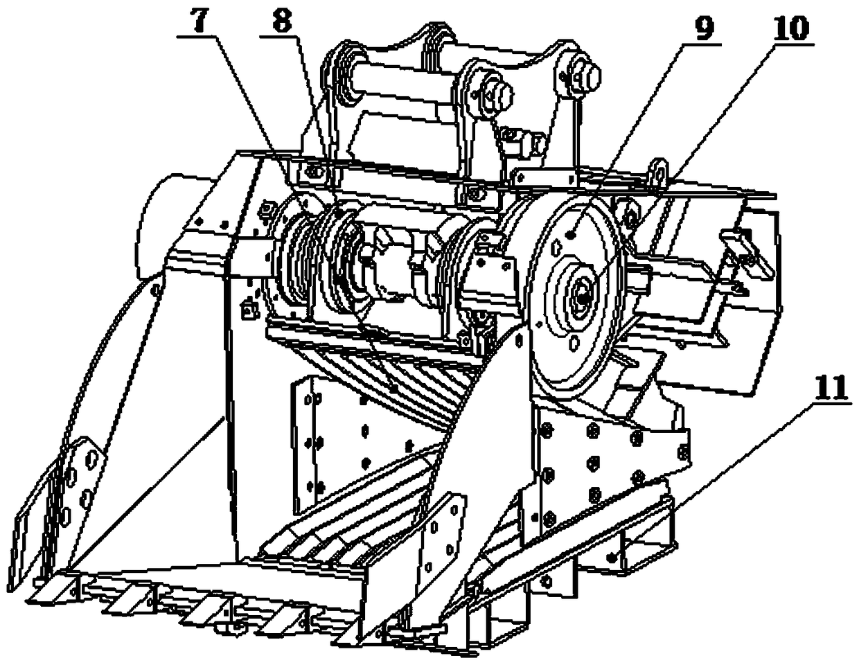
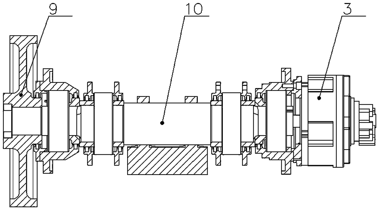
[0014] see figure 1 , figure 2 , image 3 As shown, a hydraulic crushing bucket proposed by the present invention includes a main body (1), a connector (2), a crushing mechanism, and a transmission mechanism. Each side of the main body (1) is equipped with a piece made of high-strength wear-resistant material. The baffle (4), the connector (2) is welded on the main body (1), so that the hydraulic breaker can be installed on a loader or an excavator. The crushing mechanism includes a fixed jaw (5) and a movable jaw (7), the fixed jaw (5) is fixedly connected to the inner side of the chassis (11) of the main body (1), and the movable jaw (7) is arranged on the fixed jaw (5) The opposite side and the fixed jaw plate (5) form a crushing space with a large upper end and a smaller lower end. The transmission mechanism includes a hydraulic mo...


PUM


Abstract

The invention discloses a hydraulic crushing bucket. The hydraulic crushing bucket comprises a main body. A joint is welded on the main body. The main body can be reliably installed on a loader or anexcavator through the joint. The main body comprises a crushing mechanism and a transmission mechanism. The crushing mechanism comprises a fixed jaw plate and a movable jaw plate. The fixed jaw plateis fixedly connected to the inner side of a main body bottom frame. The movable jaw plate is arranged on the other opposite side of the fixed jaw plate, and the movable jaw plate and the fixed jaw plate form a big-end-up crushing space. The transmission mechanism comprises a hydraulic motor, an inertia wheel, an eccentric shaft and an installation fixing piece. The hydraulic motor rotates to drivethe rotation of the eccentric shaft so as to drive the reciprocating motion of the movable jaw plate. By the adoption of the scheme, the crushing bucket can be reliably installed on an excavator or aloader for use, can carry out crushing work in any occasion and is small in size, light in weight, convenient to move, large in crushing force, easy to operate and low in cost.

Description

technical field [0001] The invention relates to an engineering machinery accessory, in particular to a hydraulic breaking bucket which can be installed on an excavator or a loader. Background technique [0002] At present, large-scale crushing equipment has been widely used in mines, quarries and other occasions to provide stones for concrete construction and road paving. Although the ability to process materials per unit time is strong, there are the following disadvantages: 1. The equipment is large in size, heavy in weight, high in power, difficult to fix the installation position and difficult to move; 2. Most of the crushing equipment on the market realizes the crushing function through belt transmission. Small crushing force; 3. In some special occasions such as limited space and narrow and uneven roads, large-scale crushing equipment cannot enter, and the crushing work cannot be carried out; 4. In addition, short-term crushing of stones and buildings is required in ur...

Claims


Application Information

Patent Timeline
Patent Type & Authority Applications(China)
IPC IPC(8): E02F5/30
CPCE02F5/30E02F5/305
Inventor 高峰何辉旺申增瑞王磊孙佳俊朱甲哲孙寅虎秦淑萍
Owner 南阳红阳远大重工有限公司
Learn More