Mount for installing structure, and solar cell system

A technology of solar cells and structures, applied in solar heating systems, solar thermal power generation, solar thermal energy, etc., can solve the problems of corrosion of metal parts, moisture of metal parts, increase of assembly hours, etc., and achieve the effect of improving load resistance

Inactive Publication Date: 2011-11-09
SHARP KK
View PDF9 Cites 2 Cited by
  • Summary
  • Abstract
  • Description
  • Claims
  • Application Information

AI Technical Summary

Problems solved by technology

In this case, if only the solar cell module 205 is placed on the mounting frame 203, the solar cell module 205 will slide down on the mounting frame 203, so the positioning of the solar cell module 205 is difficult.
Therefore, it is preferable to provide a stopper or the like for the solar cell module 205 on the mounting frame 203, but even if such a stopper is provided, the number of parts and the number of assembly man-hours are increased, and the assembly work is difficult or the cost increases.
[0012] Furthermore, w

Method used


Image

  • Mount for installing structure, and solar cell system
  • Mount for installing structure, and solar cell system
  • Mount for installing structure, and solar cell system

Examples


Embodiment Construction

[0091] Hereinafter, embodiments of the present invention will be described in detail with reference to the drawings.

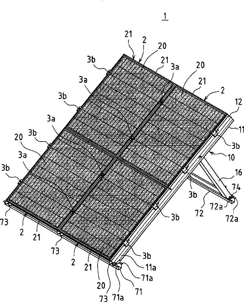
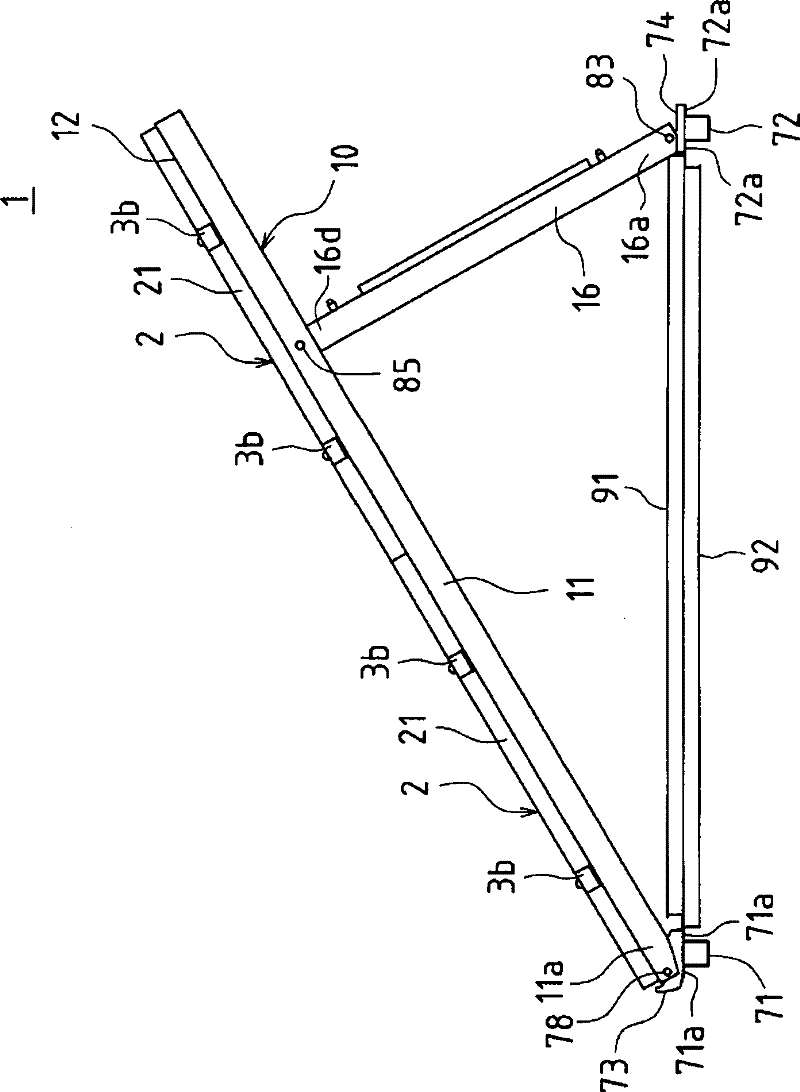
[0092] figure 1 It is a perspective view showing a solar cell system according to an embodiment using the structure mounting bracket of the present invention. also, figure 2 It is a side view showing a bracket provided for the structure of this embodiment.

[0093] Such as figure 1 As shown, in the solar battery system 1, two base rails 71, 72 are fixed to a flat roof, etc., three structure installation supports 10 are arranged side by side on each base rail 71, 72, and each structure installation support 10 is loaded Place and fix four solar battery modules 2 .

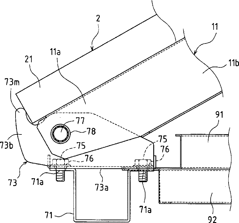
[0094] Each base rail 71, 72 has a hat-shaped cross-sectional shape, and the hat-shaped opening side faces upward. The flange-shaped flat plate portions 71a, 72a on the side are positioned on the same two-dimensional plane, and the flange-shaped flat plate portions 71a, 72a of the respective ...


PUM


Abstract

On the assumption that a mount having a triangular structure is used, even without particularly increasing the number of components, strength between the leading edge section of a placing frame and a bracket is improved, positioning of a solar cell module is facilitated, and furthermore, the bracket and fittings at the vicinity of the bracket are prevented from corroding. In an abutting section (73m) of a front bracket (73), a frame member (21) of a solar cell module (2) is positioned by being protruded to the side of the abutting section (73m) from a bottom plate (73a) of the front bracket (73). Thus, even when rain water enters between the solar cell module (2) and a placing frame (11), the rain water gradually flows on the bottom surface of the solar cell module (2), and the rain water drips as a water drop (W) from an end section of the solar cell module (2), the water drop (W) does not drop on the bottom plate (73a) of the front bracket (73) and a base rail (71).

Description

technical field [0001] The present invention relates to a structure installation frame suitable for installing a flat structure such as a solar cell module on the ground or a flat roof, and a solar cell system using the structure installation frame. Background technique [0002] In such a conventional rack, in order to support the solar cell module toward the sun, a mounting frame is fixed obliquely to a base surface such as the ground or a flat roof, and the solar cell module is supported on the inclined mounting frame. For example, if Figure 41 As shown, the two base blocks 201 and 202 are fixed separately, the front end portion 203a of the frame 203 for loading is connected and fixed to the front base block 201, and the upper end portion 204a of the vertical frame 204 is connected to the frame 203 for self-loading. 1 / 4 of the upper end of the vertical frame 204, and the lower end 204b of the vertical frame 204 is connected to the rear base block 202, and the vertical fra...

Claims


Application Information

Patent Timeline
IPC IPC(8): E04D13/18E04D13/00H01L31/042
CPCY02E10/50F24J2/5233H01L31/0424Y02E10/47F24J2/4614Y02B10/12H01L31/0422F24S25/13F24S40/44H02S20/10H02S20/24H02S30/10Y02B10/10
Inventor 嵯峨山健一大越泰
Owner SHARP KK
Why Eureka
Try Eureka