
Rotor used for double-rotor continuous mixing mill and mixing mill with same

A kneader and double-rotor technology, applied in the field of polymer processing machinery, can solve the problems of difficult control of material mixing process, material accumulation and retention, etc., and achieve the goal of improving distributed mixing capacity, preventing accumulation and stagnation, and prolonging residence time Effect

Active Publication Date: 2011-11-16
EAST CHINA UNIV OF SCI & TECH
View PDF5 Cites 19 Cited by
  • Summary
  • Abstract
  • Description
  • Claims
  • Application Information

AI Technical Summary

Problems solved by technology

[0007] The technical problem to be solved by the present invention is to provide a rotor for a double-rotor continuous mixer and a mixer including it in order to overcome the defects that the material mixing process in the prior art is not easy to control and is prone to material accumulation and retention

Method used


Image

  • Rotor used for double-rotor continuous mixing mill and mixing mill with same
  • Rotor used for double-rotor continuous mixing mill and mixing mill with same
  • Rotor used for double-rotor continuous mixing mill and mixing mill with same

Examples


Embodiment Construction

[0035] The preferred embodiments of the present invention are given below in conjunction with the accompanying drawings to describe the technical solution of the present invention in detail.

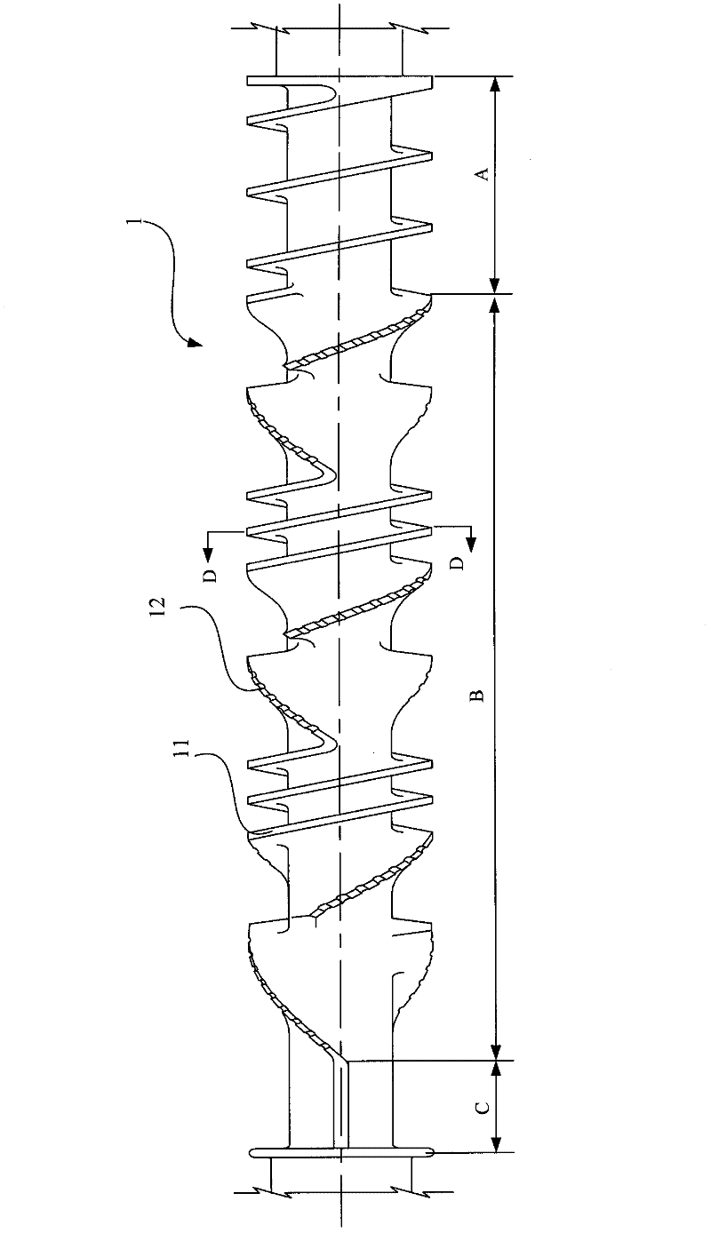
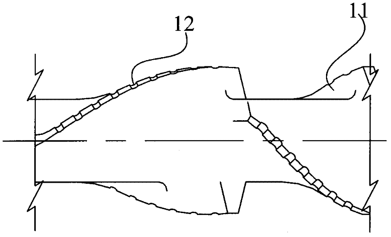
[0036] Such as figure 1 As shown, the present invention is a rotor 1 for a twin-rotor continuous mixer. The rotor 1 includes a threaded feeding section A, a mixing section B and a discharging section C from right to left in the axial direction. There are at least three mixing sections B, such as figure 2 As shown, each kneading section has at least one pair of discontinuous flights 11 with opposite directions and different helix angles, and the discontinuous flights 11 are non-meshed or tangent to each other.

[0037] Further, each kneading section has 1 to 5 pairs of discontinuous flights with opposite directions and different helix angles. Each pair of discontinuous screw flights 11 may intersect each other in the axial direction, or there may be gaps, but they are not connected to...


PUM


Abstract

The invention discloses a rotor used for a double-rotor continuous mixing mill. The rotor comprises a whorled charging section, at least three mixing sections and a discharging section along axial direction in sequence from right to left, wherein each mixing section is provided with at least one pair of discontinuous thread edges which have opposite directions and different spiral angles. The discontinuous thread edges are unengaged or tangent to each other. The invention also discloses a double-rotor continuous mixing mill with the roller. More than two mixing sections are arranged in the roller, thereby prolonging the retention time of material in a mixing chamber. By controlling the temperature, the non-molten solid phase of the material unspecific mixing chambers is pre-covered and mixed. The structure of the rotor with unengaged or tangent thread edges is adopted, thereby efficiently preventing materials from accumulating and stagnating and promoting the distributing mixing capability of the rotor.

Description

technical field [0001] The invention relates to the field of high polymer processing machinery, in particular to a rotor for a double-rotor continuous mixer and a mixer including the same. Background technique [0002] The double-rotor continuous mixer is a continuous mixing machine developed by the Farrel Company of the United States in the mid-1960s. The machine is mainly composed of barrel, rotor, unloading device and other parts. The mixing chamber on the barrel is two interconnected holes with an ∞ cross-section. The material is sheared, pulverized, kneaded and mixed by the rotor in the mixing chamber. There are also cooling water holes on the barrel and an electric heater, which can heat and cool the material according to the needs of the process. The rotor of a typical double-rotor continuous mixer can be divided into a feeding section, a mixing section and a discharging section according to its function. Among them, the feeding section is like two non-meshing twi...

Claims


Application Information

Patent Timeline
IPC IPC(8): B29B7/46
CPCB29B7/489B29C48/60B29C48/605B29C48/67
Inventor 谢林生马玉录沙金杨高品
Owner EAST CHINA UNIV OF SCI & TECH
Learn More