Tray of automatic feeding device

An automatic feeding and tray technology, applied in the direction of vibrating conveyors, conveyors, conveyor objects, etc., can solve the problems such as the quality of the shaft inserted into the motor bottom plate of the transformer, the insertion depths are different, and the shaft is loose, etc. Reasonable structural design, reducing labor and improving work efficiency

Inactive Publication Date: 2011-11-16
GUANGDONG GALANZ GRP CO LTD
View PDF6 Cites 14 Cited by
  • Summary
  • Abstract
  • Description
  • Claims
  • Application Information

AI Technical Summary

Problems solved by technology

The traditional operation method is to manually insert the shaft rod into the motor bottom plate of the transformer, and press the shaft rod firmly, which requires a lot of workers to work by hand. This operation method greatly increases the cost of labor and cannot guarantee the transformer. The quality of the shaft inserted into the motor bottom plate often has problems such as loose shafts and different insertion depths. To solve the problems, people hope to develop an auto

Method used


Image

  • Tray of automatic feeding device
  • Tray of automatic feeding device
  • Tray of automatic feeding device

Examples


Embodiment Construction

[0015] The invention will be described in further detail below in conjunction with the accompanying drawings.

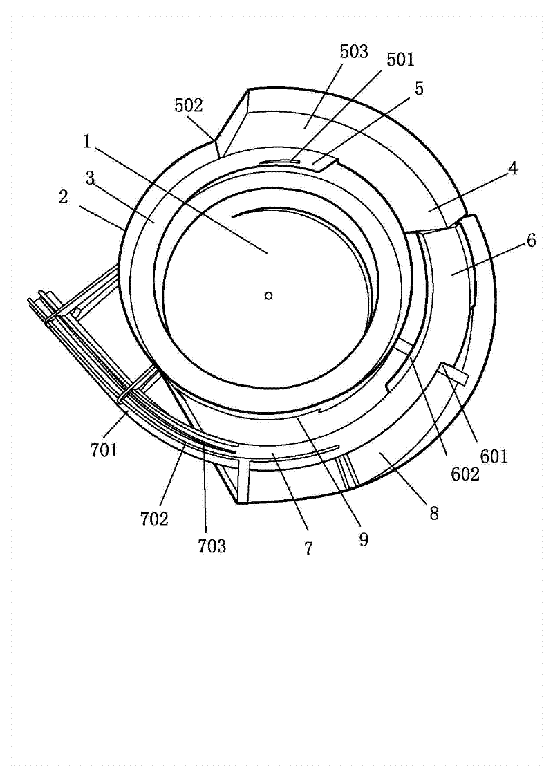
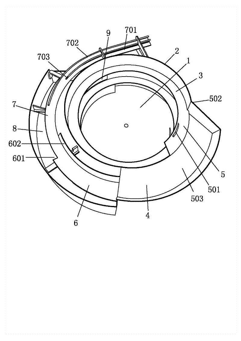
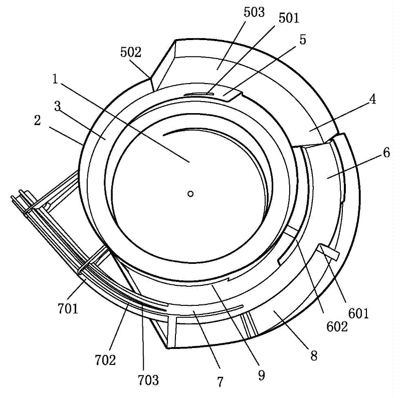
[0016] Such as Figure 1 to Figure 2 As shown, a material tray of an automatic feeding device includes a disk surface 1 and a side wall 2 surrounding the disk surface 1. The disk surface 1 is a conical surface with a convex center, and the spare parts move around the periphery of the disk surface 1. The rising feeding track 3, the feeding end of the feeding track 3 is located at the lower part of the disk surface 1, the spare parts enter the feeding track 3 from the low point, and the outer side of the side wall 2 is provided with a monolithic track 4, the feeding track 3 The discharge end of the material is connected with the monolithic track 4, and the monolithic track 4 at least includes a along section 5, a sorting section 6 and a sorting section 7. The outer periphery of the monolith track 4 is provided with a collecting groove 8, which is integrated with the m...


PUM


Abstract

The invention relates to a tray of an automatic feeding device. The material disk comprises a tray surface and a side wall around the tray surface, wherein a spiral rising loading track is arranged on the inner side of the side wall, the feeding end of the loading track is positioned in the lower position on the disk surface, a material arranging track is arranged on the outer side of the side wall, the discharging end of the loading track is connected with the material arranging track and the material arranging track at least comprises an edge-following section, a sorting section and a sequencing section. The tray of the automatic feeding device has the advantages of greatly reducing manual work, improving working efficiency and simultaneously reducing production cost.

Description

technical field [0001] The invention relates to the automatic production of spare parts of a microwave oven, in particular to a material tray of an automatic feeding device for a plug-in terminal of a transformer. Background technique [0002] Parts and accessories for microwave ovens, such as the motor base plate of the transformer, need to insert a shaft into the motor base plate of the transformer during processing. The traditional operation method is to manually insert the shaft rod into the motor bottom plate of the transformer, and press the shaft rod firmly, which requires a lot of workers to work by hand. This operation method greatly increases the cost of labor and cannot guarantee the transformer. The quality of the shaft inserted into the motor bottom plate often has problems such as loose shafts and different insertion depths. To solve the problems, people hope to develop an automatic shaft insertion machine, which can carry out automated production, reduce labor...

Claims


Application Information

Patent Timeline
IPC IPC(8): B65G27/02B65G47/24B65G47/26
Inventor 刘洪彬杨陆军张力杨世通
Owner GUANGDONG GALANZ GRP CO LTD
Why Eureka
Try Eureka