Double-stage heat storage trough type solar thermal power generation system

A trough solar and thermal power generation system technology, applied in the field of solar thermal power generation, can solve the problems of high average heat absorption temperature of mirror field, high temperature resistance performance of heat transfer oil, and large investment in heat transfer oil, so as to reduce investment and power generation costs, The effect of reducing the mirror field area and reducing the investment cost

Inactive Publication Date: 2011-11-16
INST OF ENGINEERING THERMOPHYSICS - CHINESE ACAD OF SCI
View PDF6 Cites 20 Cited by
  • Summary
  • Abstract
  • Description
  • Claims
  • Application Information

AI Technical Summary

Problems solved by technology

[0008] In view of this, the main purpose of the present invention is to provide a two-stage heat storage trough solar thermal power generation system to solve the problem of reduced heat collection efficiency caused by the high average heat absorption temperature of the mirror field, and to solve the problem of the mirror field being resistant to heat transfer oil. High temperature performance, large investment in heat transfer oil and high cost of power generation

Method used


Image

  • Double-stage heat storage trough type solar thermal power generation system
  • Double-stage heat storage trough type solar thermal power generation system
  • Double-stage heat storage trough type solar thermal power generation system

Examples


Embodiment Construction

[0035] In order to make the object, technical solution and advantages of the present invention clearer, the present invention will be described in further detail below in conjunction with specific embodiments and with reference to the accompanying drawings.

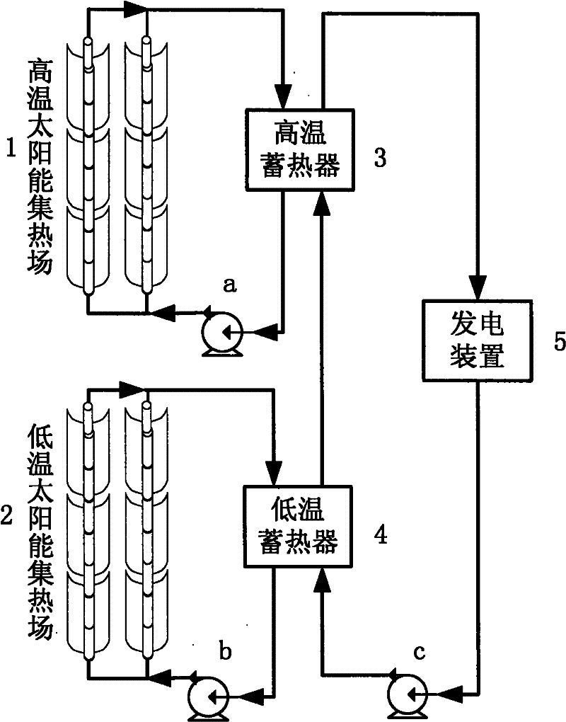
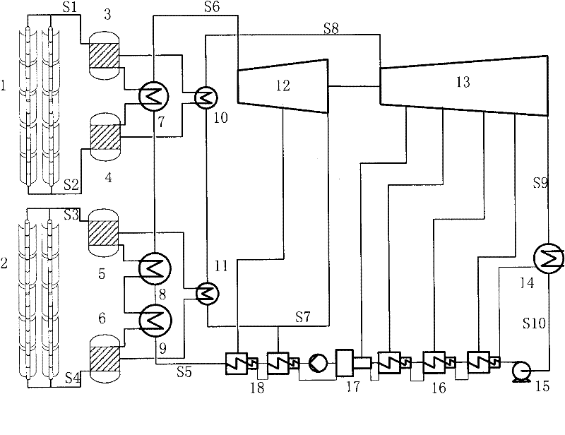
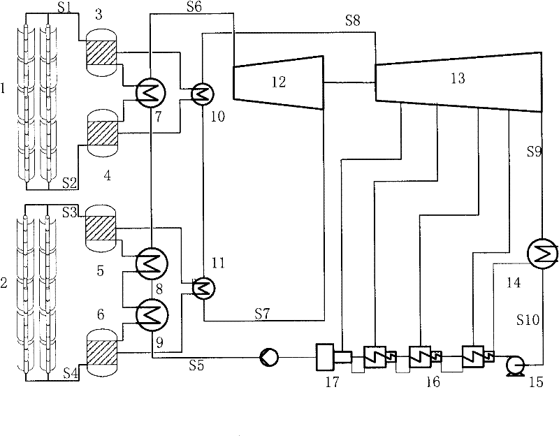
[0036] figure 1 Schematic diagram of the structure of the dual-stage heat storage trough solar thermal power generation system provided by the present invention, the system at least includes a dual-stage trough solar heat collection field, a dual-stage thermal storage subsystem and a power generation subsystem. Among them, the double-stage trough solar heat collection field includes a high-temperature heat collection field and a low-temperature heat collection field, which receive and gather solar radiation energy. Radiation energy is converted into low-temperature heat transfer oil heat; the two-stage heat storage subsystem includes a high-temperature heat accumulator and a low-temperature heat accumulator. The output l...


PUM


Abstract

The invention discloses a double-stage heat storage trough type solar thermal power generation system. The system comprises a double-stage trough type solar heat collection field, a double-stage heat storage sub-system and a power generation sub-system. The double-stage trough type solar heat collection field comprises a high-temperature heat collection field and a low-temperature heat collection field and is used for receiving and collecting solar radiation energy. The high-temperature heat collection field is used for converting the collected solar radiation energy into heat of high-temperature heat conducting oil. The low-temperature heat collection field is used for converting the solar radiation energy into heat of low-temperature heat conducting oil. The double-stage heat storage sub-system comprises a high-temperature heat accumulator and a low-temperature heat accumulator. The high-temperature heat accumulator is used for storing the high-temperature heat conducting oil output by the high-temperature heat collection field. The low-temperature heat accumulator is used for storing the low-temperature heat conducting oil output by the low-temperature heat collection field. The power generation sub-system is used for converting the heat of the heat conducting oil into steam, converting the steam into electric energy and outputting the electric energy. By using the system disclosed by the invention, a problem of reduction of heat collecting efficiency resulted from high average heat absorption temperature of a mirror field is resolved; furthermore, problems of high high-temperature resistance performance of the mirror field to the conducting oil, high investment of the conducting oil and high power generation cost are resolved.

Description

technical field [0001] The invention relates to the technical field of solar thermal power generation, in particular to a two-stage heat storage trough solar thermal power generation system. Background technique [0002] Solar thermal power generation technology has received high attention in the world and has developed rapidly. Solar thermal power generation technology is mainly divided into three types: trough type, tower type and dish type. The trough solar thermal power generation system has experience in commercial operation in the SEGS power station in the United States and the AndaSol power station in Spain. Compared with other technologies, the trough solar thermal power generation system technology is relatively mature and has the highest degree of commercialization. [0003] The main obstacle of the trough solar thermal power generation system is that the temperature of the heat-collecting working medium is not high, and the thermal efficiency of the power generat...

Claims


Application Information

Patent Timeline
Patent Type & Authority Applications(China)
IPC IPC(8): F03G6/06F24J2/34
CPCY02E10/46
Inventor 金红光韩巍高志超
Owner INST OF ENGINEERING THERMOPHYSICS - CHINESE ACAD OF SCI
Why Eureka
Try Eureka