
Focal plane detection device for projection lithography

A detection device and projection light technology, which are used in photoplate-making process exposure devices, microlithography exposure equipment, optics, etc., can solve the problems of high imaging quality requirements of CCD lenses and limited measurement range, and achieve high-precision focal plane measurement. , The effect of improving the focus detection measurement range and reducing the requirements

Inactive Publication Date: 2011-11-16
INST OF OPTICS & ELECTRONICS - CHINESE ACAD OF SCI
View PDF7 Cites 11 Cited by
  • Summary
  • Abstract
  • Description
  • Claims
  • Application Information

AI Technical Summary

Problems solved by technology

[0004] The purpose of the present invention is to provide a focal plane detection device based on coded gratings used in projection lithography to solve the problems of limited measurement range and high imaging quality requirements of CCD lens in existing lithography equipment focus detection systems

Method used


Image

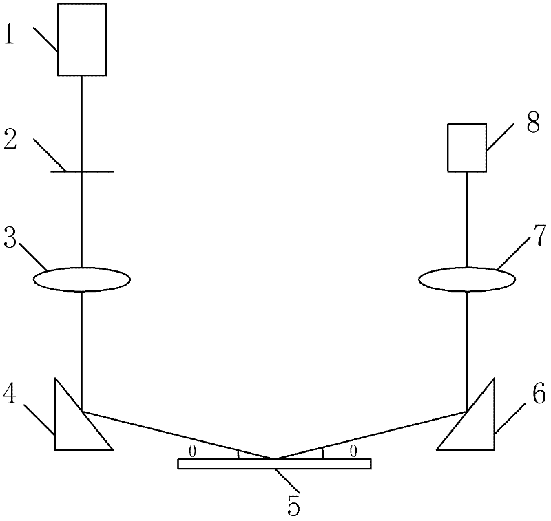
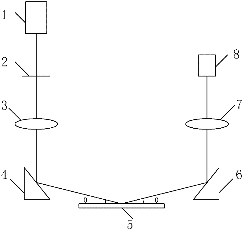
  • Focal plane detection device for projection lithography
  • Focal plane detection device for projection lithography
  • Focal plane detection device for projection lithography

Examples


Embodiment Construction

[0019] The invention uses a binary coded grating instead of a traditional slit to realize large-scale and high-precision focal plane detection.

[0020] The present invention is composed of an illumination source 1, an absolute coding grating 2, a projection imaging system 3, a first reflector 4, a surface to be measured 5, a second reflector 6, a focus detection mark amplification system 7 and a detection device 8. The light emitted by the illumination source 1 is irradiated on the absolute coded grating 2, and the light modulated by the absolute coded grating 2 passes through the projection imaging system 3 and is projected and imaged by the mirror 4 onto the surface to be measured 5, and after being reflected by the surface to be measured 5 , enters the focusing mark magnification system 7 through the mirror 6 and is received by the detection device 8 . The detector 8 is used to receive the absolute coded grating image whose position changes with the height of the surface t...


PUM


Abstract

The invention provides a focal plane detection device for projection lithography. The device is characterized in that: light emitted by a lighting source is irradiated to an absolute encoded grating; the light which is modulated by the encoded grating passes through a projection imaging system, and is projected and imaged to a surface to be detected through a first reflector; after being reflected by the surface to be detected, the light enters a focus detecting mark amplification system through a second reflector and is received by a detector; a height change of the surface to be detected changes an absolute encoded grating image received by the detector, the absolute encoded grating image is received by utilizing the detector, and absolute codes of a grating image corresponding to the height of the surface to be detected is extracted to complete detection on the position height of the surface to be detected. The focal plane detection device adopts the absolute encoded grating instead of the traditional grating slit, and reduces the coding cycle by increasing the number of code bits of the absolute encoded grating, so that the focal detection range can be enlarged, and the focus detection accuracy can be improved.

Description

technical field [0001] The invention relates to a focus detection technology in a projection photolithography system, which is based on the principle of optical triangulation and utilizes a coded grating to realize large-scale measurement of substrate height variation. Background technique [0002] Projection lithography machine is one of the important equipment for the production of large-scale integrated circuits. The projection objective lens in the projection lithography machine is the core component, and its main function is to image the graphics on the mask plate to the object to be processed in a certain proportion. Due to the limited focal depth of the projection objective lens, in order to ensure the exposure quality, it is necessary to keep the corresponding surface of the processed object within the focal depth range of the objective lens during the exposure process. For this reason, the projection lithography machine uses a focus detection system to measure the ...

Claims


Application Information

Patent Timeline
Patent Type & Authority Applications(China)
IPC IPC(8): G01M11/02G03F7/20G03F9/00
Inventor 唐燕胡松陈铭勇
Owner INST OF OPTICS & ELECTRONICS - CHINESE ACAD OF SCI
Learn More