Trigger energy saving apparatus and thyristor switch

An energy-saving device and thyristor technology, applied in electronic switches, electrical components, pulse technology, etc., can solve the problems of poor linearity of thyristor output current waveform, large power supply capacity, and increased volume, and achieve low triggering energy consumption and triggering drive energy consumption. Low, triggers the effect of reducing energy consumption

Inactive Publication Date: 2011-11-16
GUANGZHOU JINSHI ELECTRONICS
View PDF0 Cites 15 Cited by
  • Summary
  • Abstract
  • Description
  • Claims
  • Application Information

AI Technical Summary

Problems solved by technology

[0002] At present, in the power system that requires frequent switching of loads, thyristor switches are widely used to switch resistive, inductive or capacitive loads. In order to ensure the electrical isolation between the control circuit and the main circuit, the control circuit generally provides continuous pulses through the trigger transformer. trigger signal to trigger the thyristor conduction (as attached figure 1 As shown), in order to take into account the large energy consumption of the control circuit and the trigger transformer will not be saturated under high-frequency and high-current working conditions for a long time, it is generally designed under the condition of a pulse width of about 30 microseconds and a duty ratio of 1 / 3 Work, calculated in 30 microseconds here: 1.414×380×SIN (2×3.14×50×0.00003×2)=10V, it can be seen that in the 380V / 50HZ AC voltage system, the voltage at both ends of the thyristor should be Only around 10V can be reliably triggered (note: this has a certain degree of randomness), which makes the output current waveform of the thyristor poor in linearity and will generate large harmonic pollution. The triggering transformer still needs to provide a continuous triggering signal to the control mode of the thyristor (note: once the thyristor is triggered to be turned on, the triggering signal can be completely turned off, and the triggering time only needs to be in microseconds). Unnecessary waste of energy consumption makes the control circuit have the disadvantages of large power supply capacity, increased volume, and large heat generation, and electronic components that work for a long time under high-frequency, high-current, and high-temperature conditions are also prone to aging and damage

Method used


Image

  • Trigger energy saving apparatus and thyristor switch
  • Trigger energy saving apparatus and thyristor switch
  • Trigger energy saving apparatus and thyristor switch

Examples


Embodiment Construction

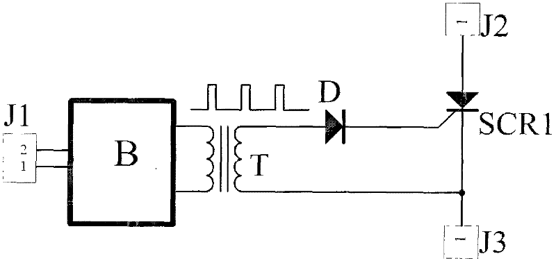
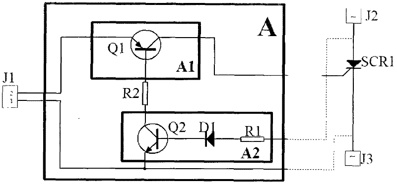
[0028] as attached figure 2 As shown, J1 is the trigger signal input terminal, the input trigger signal is connected to the thyristor SCR1 through the trigger energy-saving device (A), and the trigger energy-saving device (A) includes an electronic switch (A1), a voltage detection circuit (A2), an electronic switch ( A1) connected in series with the trigger circuit of the thyristor SCR1 to be controlled; the input terminal of the voltage detection circuit (A2) is connected to both ends of the thyristor SCR1, and the output terminal of the voltage detection circuit (A2) is connected to the electronic switch (A1) through a current limiting resistor R2 (Note: R2 is a non-essential component, and it can be used when the electronic switch (A1) or the voltage detection circuit (A2) has a built-in current-limiting component, such as transistors Q1 and Q2, which use built-in current-limiting resistors).

[0029] Electronic switch (A1): Built-in transistor Q1 (note: attached figure ...


PUM


Abstract

The invention, which belongs to the electric switch field, discloses a trigger energy saving apparatus and a thyristor switch, and especially a trigger energy saving apparatus applied in a thyristor switch trigger loop triggered by a transformer and the thyristor switch which comprises the trigger energy saving apparatus. In the invention, the trigger energy saving apparatus triggers the thyristor to be conducted only under a condition that voltage values across two ends of a thyristor are greater than the value of a thyristor conduction voltage drop. A thyristor trigger control signal is immediately closed after the thyristor conducts so that energy consumption of triggering signals can be substantially reduced, temperature rise of a control circuit can be reduced and reliability of the control circuit can be raised. In the thyristor switch comprising the trigger energy saving apparatus, because of the low energy consumption of the thyristor trigger drive, a pulse signal frequency and pulse signal duty cycle of the trigger transformer can be raised, or rectification is performed on an output signal of the trigger transformer and capacitive stored energy is given to a thyristor control terminal through the trigger energy saving apparatus. The thyristor switch possesses the following advantages of low trigger energy consumption, good conduction linearity, little harmonic wave amount and high reliability.

Description

technical field [0001] The trigger energy-saving device and the thyristor switch of the present invention belong to the field of electric switches, in particular a trigger energy-saving device suitable for use in the thyristor switch trigger circuit triggered by a transformer and a trigger energy saving device with extremely low energy consumption, good linearity, and small and reliable generation of harmonics high performance thyristor switches. Background technique [0002] At present, in the power system that requires frequent switching of loads, thyristor switches are widely used to switch resistive, inductive or capacitive loads. In order to ensure the electrical isolation between the control circuit and the main circuit, the control circuit generally provides continuous pulses through the trigger transformer. trigger signal to trigger the thyristor conduction (as attached figure 1 As shown), in order to take into account the large energy consumption of the control cir...

Claims


Application Information

Patent Timeline
Patent Type & Authority Applications(China)
IPC IPC(8): H03K17/687
Inventor 郭桥石
Owner GUANGZHOU JINSHI ELECTRONICS
Why Eureka
Try Eureka