Power control method of uplink signals, network side equipment and user equipment

A technology for network side equipment and user equipment, applied to the power control of uplink signals, network side equipment and user equipment fields, can solve problems affecting UE, inaccurate signal transmission power estimation, and uplink signal receiving user interference, etc., to reduce Effects of interference and accurate path loss

Active Publication Date: 2011-11-16
ZTE CORP
View PDF6 Cites 48 Cited by
  • Summary
  • Abstract
  • Description
  • Claims
  • Application Information

AI Technical Summary

Problems solved by technology

[0007] However, in a distributed multi-antenna system or an uplink coordinated multi-point transmission (Uplink Coordinate multi-point transmission, UL CoMP for short) system, since the receiving node of the uplink signal at the UE end may not be consistent with the sending node of the downlink signal, when the UE end When the receiving node of the uplink signal is inconsistent with the sending node of the downlink signal, the PL value estimated based on the reference signal sent by the downlink sending node will be quite different from the actual PL value between the uplink receiving node and the UE. Using the estimated PL value to estimate the transmission power of the uplink UE-side signal will cause inaccurate estimation of the UE-side signal transmission power, which will affect the reception of the UE's uplink signal and cause interference to users in adjacent cells.

Method used


Image

  • Power control method of uplink signals, network side equipment and user equipment
  • Power control method of uplink signals, network side equipment and user equipment
  • Power control method of uplink signals, network side equipment and user equipment

Examples


Embodiment 1

[0082] This embodiment is a specific example for mode one;

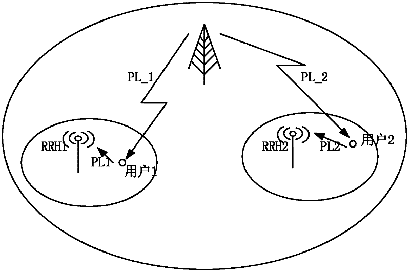
[0083] Such as figure 1 As shown, there are two users in a serving cell, denoted as UE1 and UE2. Among them, the downlink path loss from UE1 to the serving cell base station is denoted as PL_1, and the downlink path loss from UE2 to the serving cell base station is denoted as PL_2. The RRHs (Remote Radio Heads) closest to the two UEs are denoted as RRH1 and RRH2, respectively. The path loss of the uplink from RRH1 to UE1 is denoted as PL1, and the path loss of the uplink from RRH2 to UE2 is denoted as PL2. In the scenario shown in the figure, the path losses PL_1 and PL_2 of the downlink are much larger than the actual path losses PL1 and PL2 of the uplink channel.

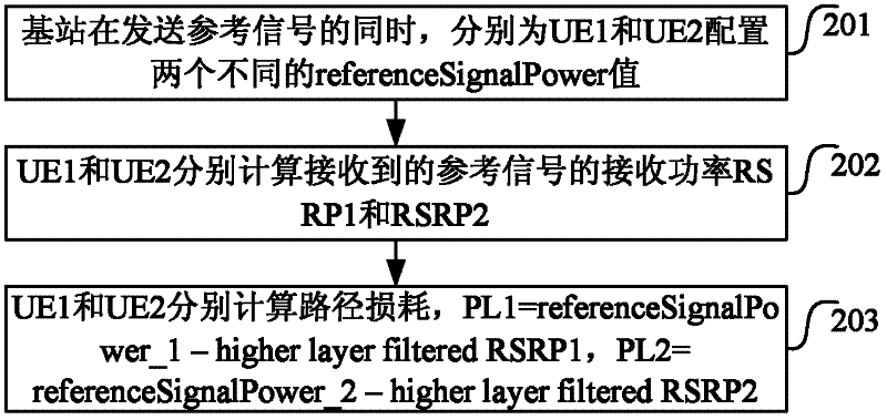
[0084] Such as figure 2 The power control method shown in this embodiment includes:

[0085] Step 201: While sending the reference signal, the base station configures two different referenceSignalPower values ​​for UE1 and UE2 respectively, which are record...

Embodiment 2

[0089] This embodiment is a specific example for mode two;

[0090] Such as figure 1 As shown, there are two users in a serving cell, denoted as UE1 and UE2. Among them, the downlink path loss from UE1 to the serving cell base station is denoted as PL_1, and the downlink path loss from UE2 to the serving cell base station is denoted as PL_2. The RRHs closest to the two UEs are denoted as RRH1 and RRH2. The uplink path loss from RRH1 to UE1 is denoted as PL1, and the uplink path loss from RRH2 to UE2 is denoted as PL2. In the scenario shown in the figure, the path losses PL_1 and PL_2 of the downlink are much larger than the actual path losses PL1 and PL2 of the uplink channel.

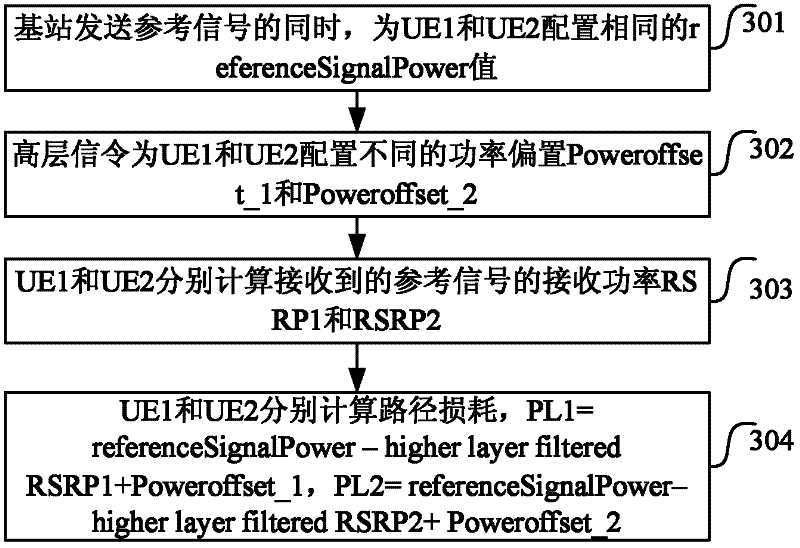
[0091] Such as image 3 The power control method shown in this embodiment includes:

[0092] Step 301: When the base station sends the reference signal, it configures the same referenceSignalPower value for UE1 and UE2, which is recorded as referenceSignalPower;

[0093] Step 302: High-level signaling confi...

Embodiment 3

[0097] This embodiment is a specific example for mode three;

[0098] Such as figure 1 As shown, there are two users in a serving cell, denoted as UE1 and UE2. Among them, the downlink path loss from UE1 to the serving cell base station is denoted as PL_1, and the downlink path loss from UE2 to the serving cell base station is denoted as PL_2. The RRHs closest to the two UEs are denoted as RRH1 and RRH2. The uplink path loss from RRH1 to UE1 is denoted as PL1, and the uplink path loss from RRH2 to UE2 is denoted as PL2. In the scenario shown in the figure, the path losses PL_1 and PL_2 of the downlink are much larger than the actual path losses PL1 and PL2 of the uplink channel.

[0099] Such as Figure 4 The power control method shown in this embodiment includes:

[0100] Step 401: When the base station sends the reference signal, it configures the same referenceSignalPower value for UE1 and UE2, which is recorded as referenceSignalPower;

[0101] Step 402: high-layer signaling co...


PUM


Abstract

The invention discloses a power control method of uplink signals, network side equipment and user equipment. The power control method comprises: the network side equipment sets reference signal power as specific parameters of the user equipment and configures the reference signal power for the user equipment. In the invention, high-layer configuration parameters (reference signal power) are set as UE-specific parameters or power offset parameter configured by high-layer signaling is added, or combined use is adopted, so that the accurate estimation on the uplink path loss is realized to ensure the reasonable uplink transmitting power of the UE and simultaneously reduce the interference of adjacent users in other cells. According to the invention, the path loss obtained by calculation is not the downlink path loss obtained by direct measurement, but the estimated value closer to the practical uplink path loss, and the practical path loss of an uplink channel can be more accurately reflected.

Description

Technical field [0001] The present invention relates to the field of mobile communication technology, and in particular to a power control method for uplink signals, network side equipment and user equipment. Background technique [0002] The uplink physical channels of the Long Term Evolution (LTE) system include: Physical Random Access Channel (PRACH), Physical Uplink Shared Channel (PUSCH) and Physical Uplink Control channel (Physical Uplink Control Channel, PUCCH for short). The uplink of LTE uses single-carrier OFDM technology, and reference signals and data are multiplexed together through TDM. The uplink reference signal is divided into: a demodulation reference signal (DM-RS) and a measurement reference signal (Sounding Reference Signal, SRS). [0003] Since the uplink of LTE adopts SC-FDMA technology, the uplink signals of different user equipment (UE) in a cell are orthogonal to each other, so the uplink power control is mainly used to compensate for the path loss (path...

Claims


Application Information

Patent Timeline
Patent Type & Authority Applications(China)
IPC IPC(8): H04W52/14H04W52/24
CPCH04W52/242H04W52/146
Inventor 任璐陈艺戬夏树强林志嵘
Owner ZTE CORP
Why Eureka
Try Eureka