Sheet cutter and belt working apparatus

A technology of processing tools and cutting devices, which is applied in metal processing and other directions, can solve problems such as falling off and dangerous situations, and achieve the effect of safe separation

Inactive Publication Date: 2011-11-16
NITTA CORP
View PDF2 Cites 4 Cited by
  • Summary
  • Abstract
  • Description
  • Claims
  • Application Information

AI Technical Summary

Problems solved by technology

And in this case, the peak-shaped front end portion of the belt also bites into the blade and does not fall off from the blade.
It is a troublesome operation to make it fall off each time, and it is dangerous to apply force with fingers near the edge

Method used


Image

  • Sheet cutter and belt working apparatus
  • Sheet cutter and belt working apparatus
  • Sheet cutter and belt working apparatus

Examples


Embodiment Construction

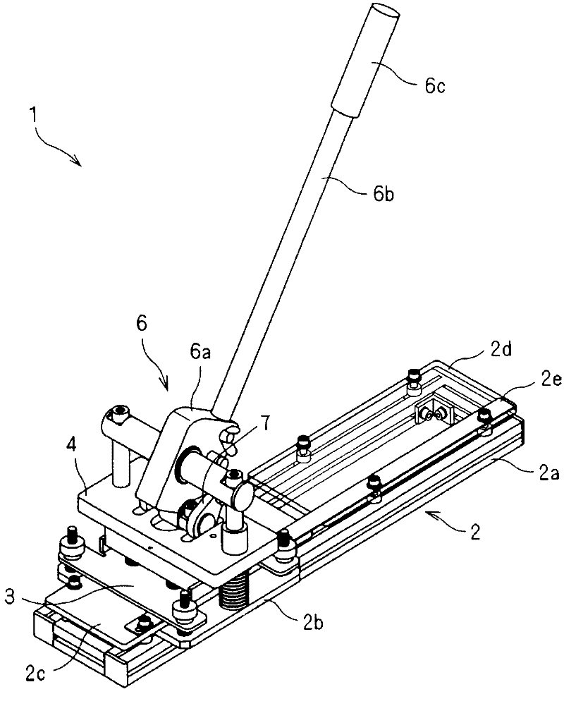
[0024] Hereinafter, a tape processing tool according to an embodiment of the present invention will be described in detail with reference to the drawings. In addition, although the cutting object of the sheet|seat cutting apparatus of this invention is a sheet, it is substantially the same as a tape processing tool.

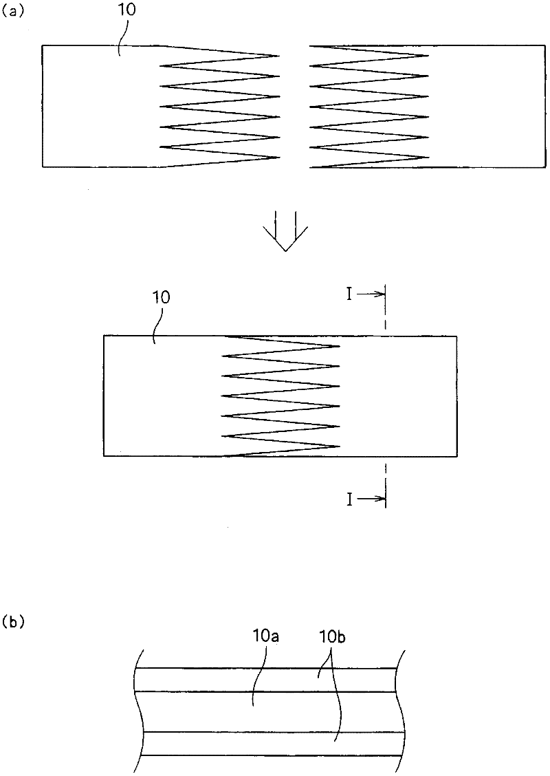
[0025] First, refer to figure 2 (a) and (b) illustrate the tape 10 cut by the tape processing tool of the present invention.

[0026] figure 2 The belt 10 shown in (a) and (b) is a long sheet with a predetermined width, and is specifically a belt used for conveying apparatuses, such as a belt conveyor and a printing machine. like figure 2 As shown in (b), the belt 10 is composed of a core material 10a and outer layers 20b laminated on both surfaces of the core material 10a. The core material 10a is formed of canvas, non-woven fabric, etc., and the outer layer 10b is formed of natural rubber, various synthetic rubbers, or thermoplastic elastomers or thermoplas...


PUM


Abstract

Provided is a sheet cutter for use, for example, in a belt working apparatus, comprising a base (2) for placing a belt, a die holder (4) for holding Thompson die at the bottom thereof, a stripper plate (3) capable of holding down the belt at a lower position and vertically movable above the base, the stripper plate being provided with a slot through which a cutting blade of the Thompson die passes, a cam plate supported by a rotatable pin supported by the base, the cam plate being provided with a cam surface that urges the die holder downward upon rotation, an operable member (6) including a lever that rotates the cam plate, a means for biasing the stripper plate upwardly and a stopper for limiting an upward motion of the stripper plate.

Description

technical field [0001] The present invention relates to a piece cutting device and a belt processing tool for cutting a piece such as a belt into a predetermined shape, and more particularly to a belt splicing tool for forming an endless flat belt by butting ends of a long flat belt. Background technique [0002] In order to butt the ends of the belt smoothly and firmly, finger joining may be employed in which the ends of the belt are cut and processed into a zigzag shape and then butted together. The finger joint has the advantage of increasing the contact area between the ends and increasing the strength of the butt joint. Patent Document 1 describes a flat belt joining method based on such finger joining. According to this joining method, the butted ends are processed into serrations respectively, and they are butted in a meshing manner (refer to figure 2 ). [0003] Patent Document 2 discloses a motor-driven shearing machine. This shearing machine is a device that ra...

Claims


Application Information

Patent Timeline
Patent Type & Authority Applications(China)
IPC IPC(8): B26D1/08B26F1/40
CPCB26D5/16B26D3/10B26D3/003B26D7/025B26D1/04B26D5/10Y10T83/215B26D1/08B26D1/06B26F1/40B26F1/44
Inventor 洼田武士
Owner NITTA CORP
Why Eureka
Try Eureka