
Braking control device

A technology of braking control and braking device, which is applied in the directions of brakes, braking components, control valves and air release valves, etc., can solve the problems that cannot be generated and cannot be satisfied at an appropriate timing, and achieve the effect of achieving control accuracy.

Active Publication Date: 2011-11-16
TOYOTA JIDOSHA KK
View PDF11 Cites 3 Cited by
  • Summary
  • Abstract
  • Description
  • Claims
  • Application Information

AI Technical Summary

Problems solved by technology

That is, when the piston pump is used as the pressure pump of the brake actuator, there will be a problem that the required brake hydraulic pressure of the wheel of the control object cannot be satisfied at an appropriate timing, and when the required brake hydraulic pressure is required for the wheel Cannot generate required braking force

Method used


Image

  • Braking control device
  • Braking control device
  • Braking control device

Examples


Embodiment

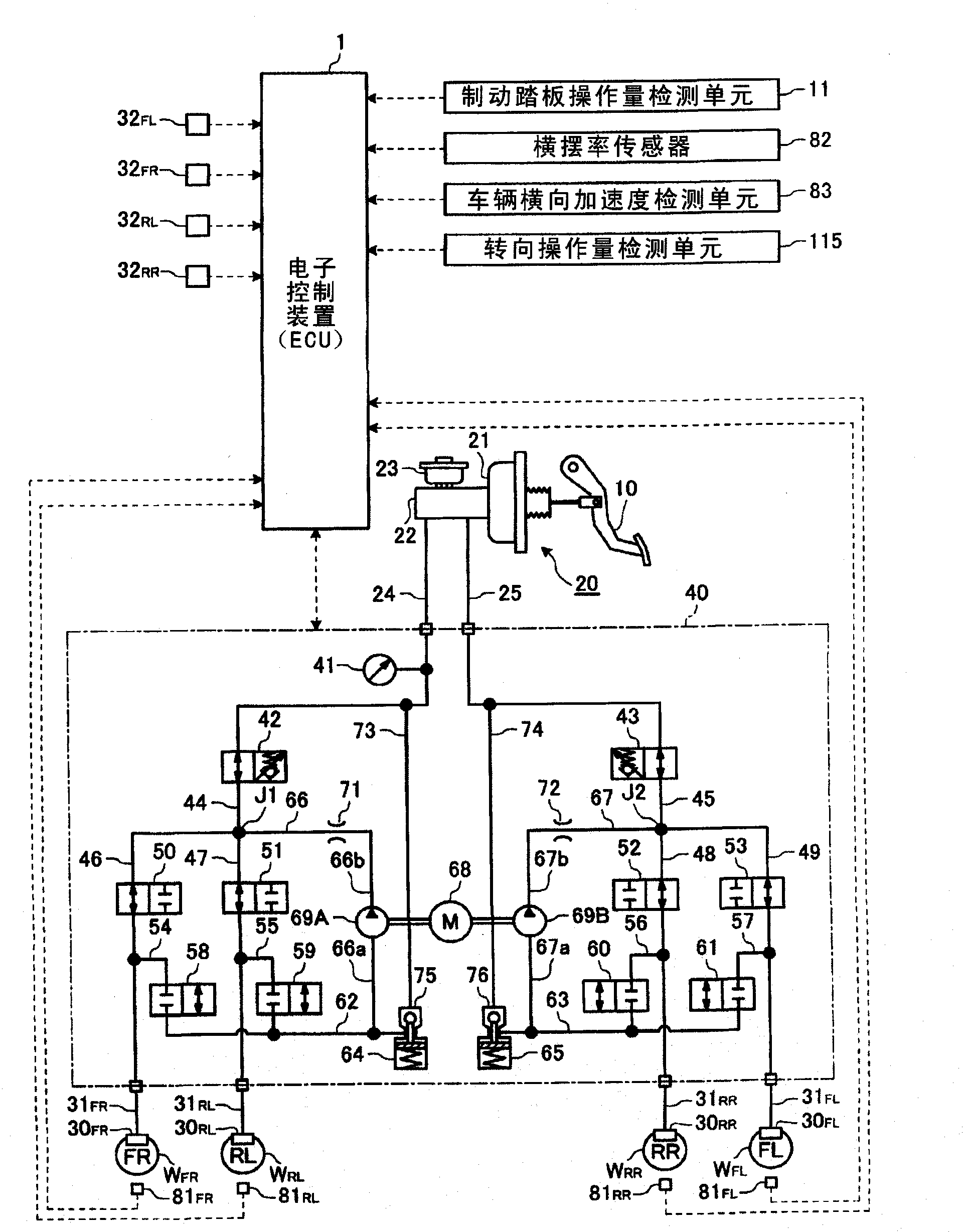
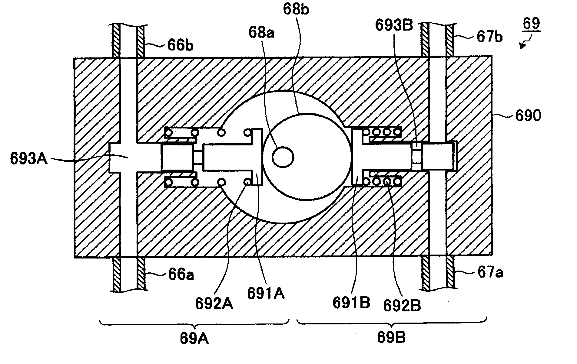
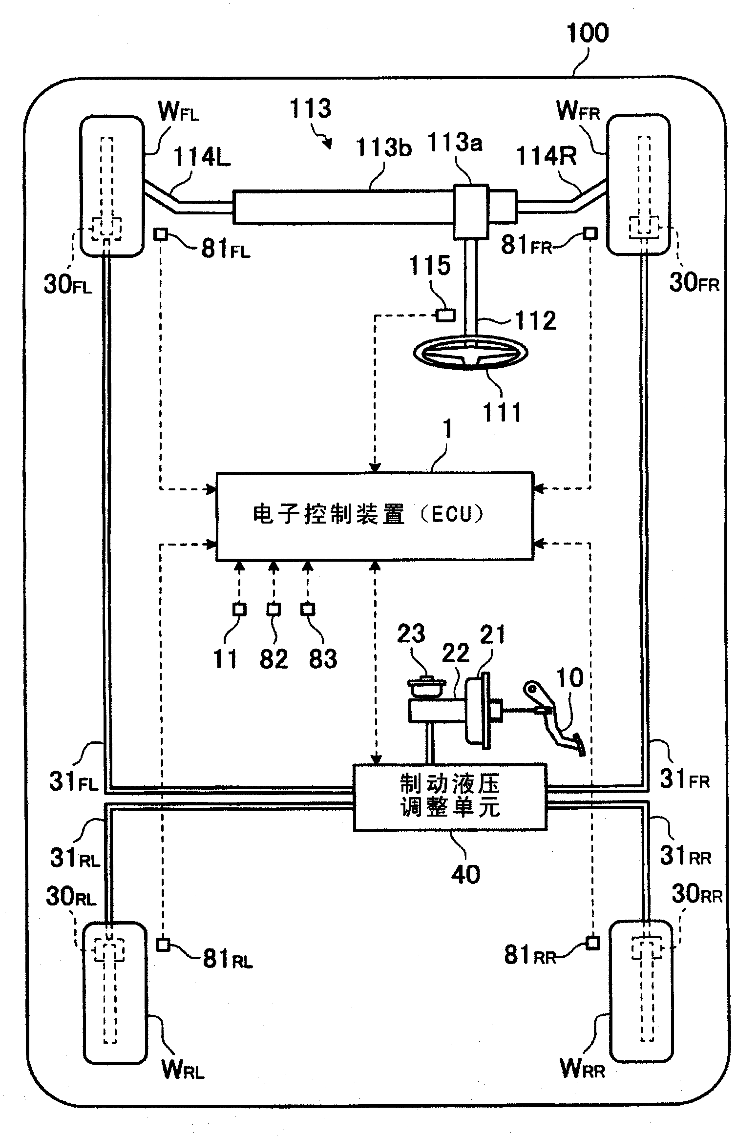
[0049] based on Figure 1 to Figure 6 Embodiments of the brake control device according to the present invention will be described.

[0050] The braking control device of the present embodiment controls the braking of each wheel W through the braking device described later. FL , W FR , W RL , W RR The braking torque (braking force) generated on is configured here as figure 1 The electronic control unit (ECU) 1 shown has one function. The electronic control device 1 includes a CPU (Central Processing Unit) not shown in the figure, a ROM (Read Only Memory) that stores predetermined control programs and the like in advance, and a RAM (Random Access Memory) that temporarily stores calculation results of the CPU. ; random access memory), and a backup RAM for storing pre-prepared information and the like.

[0051] first, figure 1 An example of a brake device to be controlled by the brake control device is shown. The vehicle is equipped with a power source such as an engine a...


PUM


Abstract

A braking control device {an electronic control device (1)} for a braking system comprises booster valves (50, 51, 52, 53) which are opened when the boost of a brake liquid pressure to be fed to control target wheels (WFR, WRL, WRR, WFL) is requested, and piston pumps (69A, 69B) for feeding a pressurized brake liquid to the upstream side of the booster valves (50, 51, 52, 53). The braking control device further comprises brake liquid pressure control means for setting a duty ratio between the opening period and the closing period of the booster valves (50, 51, 52, 53) so that the dischargeable period of the brake liquid in the piston pumps (69A, 69B) may appear in the opening period of the booster valves (50, 51, 52, 53), thereby to control the booster valves (50, 51, 52, 53) on the basis of that duty ratio.

Description

technical field [0001] The present invention relates to a brake control device for controlling the operation of a brake device using a piston pump for pressurizing brake fluid. Background technique [0002] In the past, the brake actuator of the brake device used a plurality of electromagnetic valves arranged on the passage of the brake fluid to pressurize the brake fluid supplied to the wheel to realize the pressurization of the brake fluid of the wheel. A booster pump, a motor that drives the booster pump, and the like are configured. As the pressurizing pump, there is known a gear pump that sucks and discharges brake fluid along with the rotation of gears that has been widely used in the past, and a pump that sucks and discharges brake fluid through the reciprocating motion of a piston that is excellent in cost is also known. Suction and discharge piston pumps, etc. For example, a brake device including this piston pump is described in Patent Document 1 below. In the b...

Claims


Application Information

Patent Timeline
IPC IPC(8): B60T8/00B60T8/1755B60T8/34
CPCB60T8/36B60T8/4031B60T8/5006B60T8/404B60T8/1755B60T8/4872B60T8/00B60T8/34
Inventor 渡部良知加藤英久
Owner TOYOTA JIDOSHA KK
Learn More