[0015] Now in conjunction with the accompanying drawings, the examples of the present invention will be described in detail.
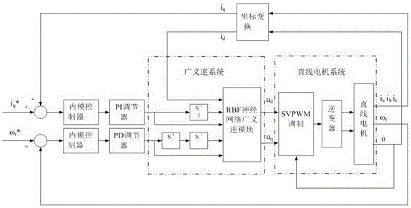
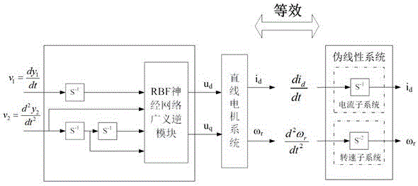
[0016] like figure 1 As shown, the generalized inverse internal model control method of linear motor RBF neural network includes: generalized inverse system, linear motor system, PI regulator, PD regulator, internal model controller, and coordinate transformation module. The generalized inverse system includes: RBF neural network generalized inverse module, current loop first-order integration module, speed loop second-order integration module; linear motor system includes: SVPWM modulation module, inverter, linear motor module.
[0017] The output end of the linear motor is measured and calculated by the photoelectric rotary encoder and the transformer used to detect the phase current to obtain the rotational speed ω r , electrical angle θ, phase current i a , i b , i c. The two rotating coordinate currents i obtained after the phase current and the electrical angle are changed by the coordinate d , i q , where i d The output is connected to the generalized inverse module of the RBF neural network, i q with the input current signal i q * phase connection; linear motor output speed ω r with the input speed signal ω r * phase connection; the output electrical angle θ of the linear motor is connected with the SVPWM modulation module.
[0018] by the feedback current i q and rotational speed ω r with the input current signal i q * and the speed signal ω r * The deviation is fed back to the internal model controller, and after being corrected by the internal model controller, it is input to the PI regulator and the PD regulator respectively for adjustment. The output quantities of the PI regulator and the PD regulator are respectively connected with the first-order integrator and the second-order integrator.
[0019] The output of the current first-order integrator, the speed second-order integrator and the i obtained through the coordinate transformation module d It is connected with the input end of the generalized inverse module of the RBF neural network to form a generalized inverse system of the linear motor; the output of the generalized inverse module of the RBF neural network is u d , u q and the electrical angle θ of the feedback terminal are respectively connected to the SVPWM modulation module to complete the decoupling and linearization of the system. figure 2 shown.
[0020] The decoupled pseudo-linear system is connected to the internal model controller to adjust the modeling parameters, and then the generalized inverse internal model control model of the linear motor RBF neural network is constructed.
[0021] In this implementation case, the combination of MATLAB/Simulink and dSPACE is used to drive a permanent magnet linear motor as an example, and the implementation of the control method of the present invention is described in detail:
[0022] Step 1: Perform data sampling on the construction of the generalized inverse module of the RBF neural network in MATLAB/Simulink, first determine the sampling signal, and when the neural network is trained [i d ,i d ´,ω r ,ω r ´,ω r ´´] constitutes the input of the neural network, [u d , u q ] constitute the output of the neural network, so only need to collect i d and ω r as a sample.
[0023] Step 2: After sampling enough training data, determine the number of layers and nodes of the selected RBF neural network, add normalization and denormalization modules before and after the RBF neural network module, and set the number of training iterations and select the appropriate training function, train the RBF neural network, and select the approximation effect by the error between the actual output and the expectation.
[0024] Step 3: Select the generalized inverse module of the RBF neural network with a good approximation effect. In the built simulation model, connect the input of the generalized inverse module of the RBF neural network with the first-order integral subsystem and the second-order integral subsystem to form a generalized inverse system .
[0025] Step 4: Build the SVPWM modulation module, inverter module, and linear motor module in the simulation model.
[0026] Step 5: Output the electrical angle θ and phase current i from the linear motor module a , i b , i c Connected with the coordinate transformation module, the coordinate transformation module outputs i d Connected to the generalized inverse module of the RBF neural network, i q with the input current signal i q * phase connection; linear motor module output speed ω r with the input speed signal ω r * The output electrical angle θ of the linear motor module is connected with the SVPWM modulation module.
[0027] Step 6: Design the internal parameters of the internal model controller to feed back the current i q and rotational speed ω r with the input current signal i q * and the speed signal ω r * The deviation is fed back to the internal model controller, and after being corrected by the internal model controller, it is input to the PI regulator and the PD regulator respectively for adjustment.
[0028] Step 7: Combine MATLAB/Simulink with RTI of dSPACE through RTW, convert the simulation model into digital drive signal by configuring parameters of each module and I/O, and convert the mathematical model in the original simulation system into a practical physical meaning The controlled object is designed, the inverter drives the linear motor, and the variable parameters of the RBF neural network generalized inverse linear motor control system are adjusted in time by observing and recording the experimental waveform.