Multi-centrifugal sheet combined type speed controller and brushless motor

A brushless motor and governor technology, applied in electrical components, electromechanical devices, magnetic circuit shape/style/structure, etc., to achieve the effect of improving the speed regulation effect, the speed regulation range is balanced and efficient, and suitable for mass production

Inactive Publication Date: 2015-09-16
江苏智远智能驱动技术研究院有限公司
View PDF5 Cites 2 Cited by
  • Summary
  • Abstract
  • Description
  • Claims
  • Application Information

AI Technical Summary

Problems solved by technology

[0005] In order to overcome the deficiencies of the original design, 1. linearize the centrifugal force curve, which can better match with the spring; Chip combined speed governor and brushless motor": including stator and winding, driving rotor and speed regulating rotor, speed governor, motor shaft, casing, etc., in which the driving rotor occupies most of the air gap of the stator and undertakes energy conversion The main function is to be fixedly connected with the motor shaft, and to output mechanical torque through the motor shaft; it is characterized in that the speed-regulating rotor is connected with the governor, and the governor includes a casing, and there are two sets of centrifugal motors in a symmetrical configuration in the casing. The disc group and the cam bushing constitute the rotational speed induction adjustment mechanism, the low-speed locking mechanism, and the torque mechanism composed of the cam bushing and the spring; the governor casing 10 has a middle partition 14, which divides the casing into two parts. It is the governor plate chamber 12 and the spring chamber 11, and there is a hole in the middle of the partition. The tooth end of the camshaft sleeve 6 is located in the governor plate chamber, and forms a speed sensing adjustment mechanism with the governor plate group; its tail end constitutes a spring shaft, and the spring shaft passes through Enter the spring chamber through the middle hole and form a torque mechanism with the scroll spring 13

Method used


Image

  • Multi-centrifugal sheet combined type speed controller and brushless motor
  • Multi-centrifugal sheet combined type speed controller and brushless motor
  • Multi-centrifugal sheet combined type speed controller and brushless motor

Examples


Embodiment Construction

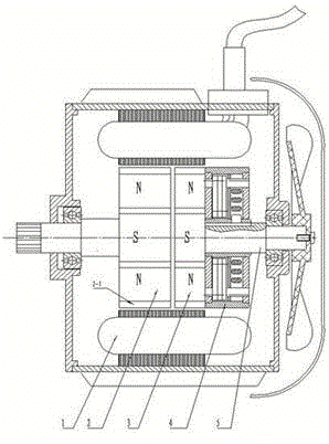
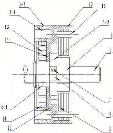
[0018] see figure 1 and figure 2 , this is a permanent magnet brushless motor with infinitely variable speed inner rotor: stator, casing, end cover, the same as ordinary brushless motors, the driving rotor 2 is placed at the output end of the motor shaft, the speed regulating rotor 2 and the governor 3 are placed after driving the rotor. The driving rotor 2 is provided with permanent magnets 2-1 in the circumferential direction, so that the polarities are periodically distributed according to N and S. The driving rotor 2 occupies most of the air gap of the stator, undertakes the main function of energy conversion, and is fixedly connected with the rotor shaft 1. The rotor shaft 1 outputs mechanical torque; the yoke 3-1 of the speed-regulating rotor 3 is provided with permanent magnets 3-2 along the circumferential direction, and the polarities are periodically distributed according to N and S, and their magnetic flux corresponds to the rest of the stator air gap . The spe...


PUM


Abstract

The invention relates to a multi-centrifugal sheet combined type speed controller and a brushless motor. The multi-centrifugal sheet combined type speed controller comprises a stator, a winding, a driving rotor, a speed control rotor, a speed controller, a motor shaft, a machine shell and the like, wherein the driving rotor occupies a large part of the area of a stator gap, plays a main role of energy conversion, is fixedly connected with the motor shaft, and outputs mechanical torque through the motor shaft. The multi-centrifugal sheet combined type speed controller is characterized in that the speed control rotor is connected with the speed controller, the speed controller comprises a shell, two groups of specifically combined centrifugal sheet groups in symmetrical configuration, a cam shaft sleeve and a spring are arranged in the shell, so that a rotating speed sensing adjusting mechanism, a low-speed locking mechanism and a torque mechanism are formed; the speed controller utilizes the principle of centrifugal force and flux weakening speed control, self-adaptive stepless speed change is realized, so that the permanent magnet brushless motor outputs a stable large torque at a low speed and can also output stable and efficient power at a high speed.

Description

technical field [0001] The invention relates to a permanent magnet brushless motor, in particular to a permanent magnet brushless motor for driving an electric vehicle. Background technique [0002] In recent years, the driving technology of electric vehicles has developed rapidly, and the driving motor plays a very important role as its heart. Various technical solutions are constantly being introduced, among which the permanent magnet brushless motor has been widely used in existing electric vehicles due to its compact structure, high specific power, high efficiency, and mature technology. [0003] However, ordinary permanent magnet brushless motors are difficult to adjust the magnetic flux of the motor, and it is difficult to have the characteristics of equal power speed regulation required for vehicle driving. The high-efficiency range of its mechanical characteristics cannot meet the variation range of the actual working conditions, which is very uneconomical. Since th...

Claims


Application Information

Patent Timeline
Patent Type & Authority Applications(China)
IPC IPC(8): H02K1/27H02K16/02H02P6/08
Inventor 杨世国杨荷
Owner 江苏智远智能驱动技术研究院有限公司
Why Eureka
Try Eureka