High-linearity delay chain

A technology of high linearity and delay chain, applied in the field of delay chain, can solve the problem of low linearity, achieve linearization and improve output accuracy

Active Publication Date: 2019-09-10
UNIV OF ELECTRONICS SCI & TECH OF CHINA
View PDF6 Cites 2 Cited by
  • Summary
  • Abstract
  • Description
  • Claims
  • Application Information

AI Technical Summary

Problems solved by technology

[0003] Aiming at the problem of low linearity in the above-mentioned traditional delay chain, the present invention proposes a delay chain, which introduces a multiplexer into a single delay unit, so that the delay unit can realize multiple delays, and at the same time use the same calibration code to control Each delay unit makes the delay time of each delay unit the same, and realizes outputting a delayed signal with high linearity

Method used


Image

  • High-linearity delay chain
  • High-linearity delay chain
  • High-linearity delay chain

Examples


Embodiment Construction

[0018] The technical solution of the present invention will be described in detail below in conjunction with the accompanying drawings and specific embodiments.

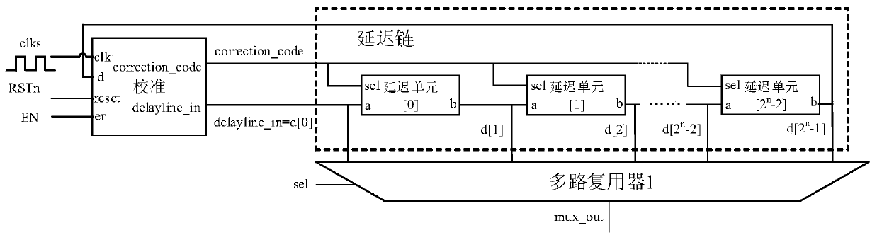
[0019] The high linearity delay chain proposed by the present invention has higher linearity than the traditional delay chain structure, and its structure is as follows figure 1 As shown, it includes a calibration block, a delay chain block, and a first multiplexer.

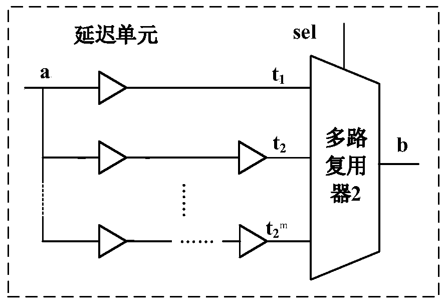
[0020] The delay chain module consists of 2 n -1 delay unit cascaded, each delay unit has a structure such as figure 2 shown, including 2 m delay paths with different delay times t 1 -t 2 m and a second multiplexer, the input end of each delay path is connected to the input end a of the delay unit, and the output end of each delay path is connected to the input end of the second multiplexer; the second multiplexer The selection terminal sel of the user is connected to the m-bit calibration code correction_code generated by the calibration module, ...


PUM


Abstract

A high-linearity delay chain comprises a calibration module, a delay chain module and a first multiplexer, and the delay chain module comprises 2n-1 cascaded delay units. Each delay unit comprises 2mdelay paths and a second multiplexer, and each delay path outputs an input signal of the delay unit to the second multiplexer after different delays; the second multiplexer selects the signal output after passing through the corresponding delay path according to the m-bit calibration code; the clock end of the calibration module is connected with a clock signal, and the calibration end of the calibration module is connected with the output end of the last cascaded delay unit, and is used for generating m-bit calibration codes, judging whether the calibration codes are added or subtracted by one when the rising edge of the clock signal comes, and transmitting the input signal of the delay chain to the input end of the first delay unit in the delay chain module; input end of first multiplexer is connected with input end of delay chain module and 2n- And the selection end of one delay unit is connected with an n-bit selection signal, and the output end of the delay unit is used as the output end of the delay chain.

Description

technical field [0001] The invention belongs to the technical field of power electronics, and in particular relates to a delay chain with high linearity. Background technique [0002] As modern technology enters the nanometer level, and the integration of circuits is getting higher and higher, and the frequency of circuits is getting faster and faster, so the optimization of timing is becoming more and more important. The delay chain structure is a typical timing structure. There are more and more digital circuits in the delay chain structure, and the requirements for the precision and linearity of the delay chain structure are also getting higher and higher. The delay chain structure has a wide range of applications, and has applications in many different structures such as phase-locked loops, digital pulse width modulators, FPGAs, and DC-DC converters. In the traditional delay chain structure, a single delay unit can only implement two delay paths, and the linearity is no...

Claims


Application Information

Patent Timeline
Patent Type & Authority Applications(China)
IPC IPC(8): H03K17/51
CPCH03K17/005H03K17/007H03K17/51
Inventor 罗萍周先立赵忠王晨阳王浩
Owner UNIV OF ELECTRONICS SCI & TECH OF CHINA
Why Eureka
Try Eureka