Driving device for vehicle

a technology for driving devices and vehicles, applied in the direction of vehicle sub-unit features, propulsion using engine-driven generators, transportation and packaging, etc., can solve the problems of power balance control failure, etc., to prevent engine rotation speed drop, control accuracy is superior, and power balance control accuracy can be controlled accurately

Active Publication Date: 2017-02-09
TOYOTA JIDOSHA KK
View PDF0 Cites 5 Cited by
  • Summary
  • Abstract
  • Description
  • Claims
  • Application Information

AI Technical Summary

Benefits of technology

[0015]According to such a configuration, when the first rotating electric machine is controlled in the rectangular wave control mode, a drop in rotation speed of the engine is prevented by restricting the requested driving force, not by restricting the function of the engine feedback control. Therefore, as compared with the case of restricting the function of the engine feedback control, the situation in which the rotation speed of the engine remains at a value higher than the target rotation speed is suppressed, and thus, the situation in which the rotation speed of the first rotating electric machine remains at a high value is also suppressed. As a result, the control mode of the first rotating electric machine can be encouraged to switch to the pulse width modulation control mode that is superior in control accuracy to the rectangular wave control mode. When the control mode of the first rotating electric machine switches to the pulse width modulation control mode, the power balance by the power balance control can be controlled accurately. On the other hand, when the first rotating electric machine is controlled in the pulse width modulation control mode, a drop in rotation speed of the engine is prevented by restricting the function of the engine feedback control, not by restricting the requested driving force. Therefore, a drop in rotation speed of the engine can be prevented without restricting the driving force.

Problems solved by technology

However, when an attempt is made to generate the driving force in a state where the engine rotation speed is deviating to the side higher than the target rotation speed during the batteryless travel control, it is concerned that the engine rotation speed drops and a power balance by the power balance control is broken.
Therefore, it is concerned that the engine rotation speed drops sharply.
When this drop in engine rotation speed Ne causes a rotation speed of the first rotating electric machine to decrease as well, it is concerned that the electric power generated by the first rotating electric machine decreases and the power balance by the power balance control is broken.
As a result, the function of the engine feedback control is restricted.

Method used


Image

  • Driving device for vehicle
  • Driving device for vehicle
  • Driving device for vehicle

Examples


first embodiment

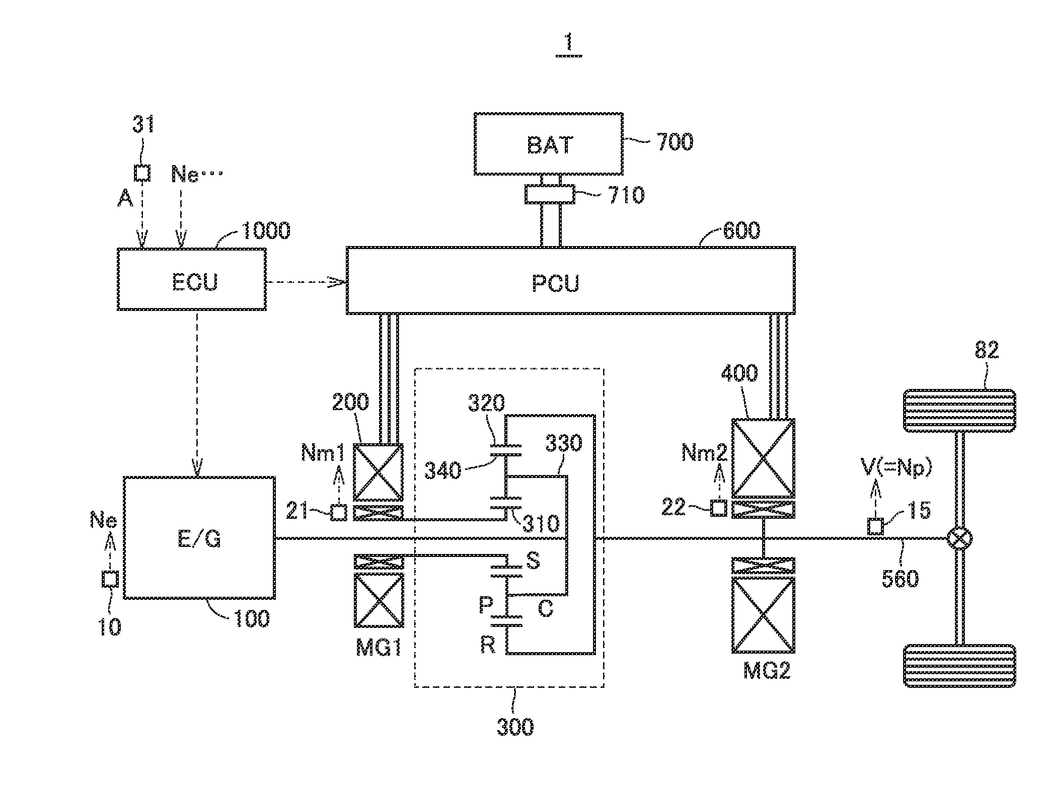
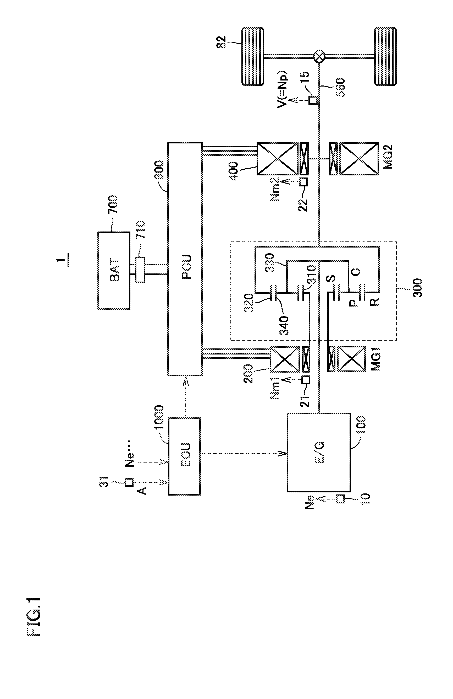
[0036]FIG. 1 is an overall block diagram of a vehicle 1 according to the present embodiment. Vehicle 1 includes an engine 100, a first MG (Motor Generator) 200, a power split device 300, a second MG 400, an output shaft 560, driving wheels 82, a PCU (Power Control Unit) 600, a battery 700, an SMR (System Main Relay) 710, and an ECU (Electronic Control Unit) 1000.

[0037]Engine 100 is an internal combustion engine that burns a fuel and outputs the motive power. Each of first MG 200 and second MG 400 is an AC rotating electric machine and functions both as a motor and a generator. Hereinafter, a rotation speed of engine 100 may be denoted as “engine rotation speed Ne”, a rotation speed of first MG 200 may be denoted as “first MG rotation speed Nm1”, and a rotation speed of second MG 400 may be denoted as “second MG rotation speed Nm2”. In addition, the torque of engine 100 may be denoted as “engine torque Te”, the torque of first MG 200 may be denoted as “first MG torque Tm1”, and the t...

second embodiment

[0118]In the first embodiment described above, a drop in engine rotation speed Ne has been prevented by restricting requested driving force Preq used for the power balance control, in a case where engine rotation speed Ne deviates to the side higher than target rotation speed Nereq during the batteryless travel control.

[0119]However, when requested driving force Preq is great, a drop in engine rotation speed Ne may be prevented by restricting the function of the engine F / B control (function of decreasing engine rotation speed Ne toward target rotation speed Nereq), instead of restricting requested driving force Preq, in order to satisfy the user's request.

[0120]As the specific process for restricting the function of the engine F / B control, at least one of a process for decreasing a feedback gain K and a process for increasing target rotation speed Nereq may be executed.

[0121]When the process for decreasing feedback gain K is executed, the speed of decrease in engine torque Te (throt...

third embodiment

[0127]In the second embodiment described above, a drop in engine rotation speed Ne has been prevented by restricting the function of the engine F / B control in a case where engine rotation speed Ne deviates to the side higher than target rotation speed Nereq during the batteryless travel control.

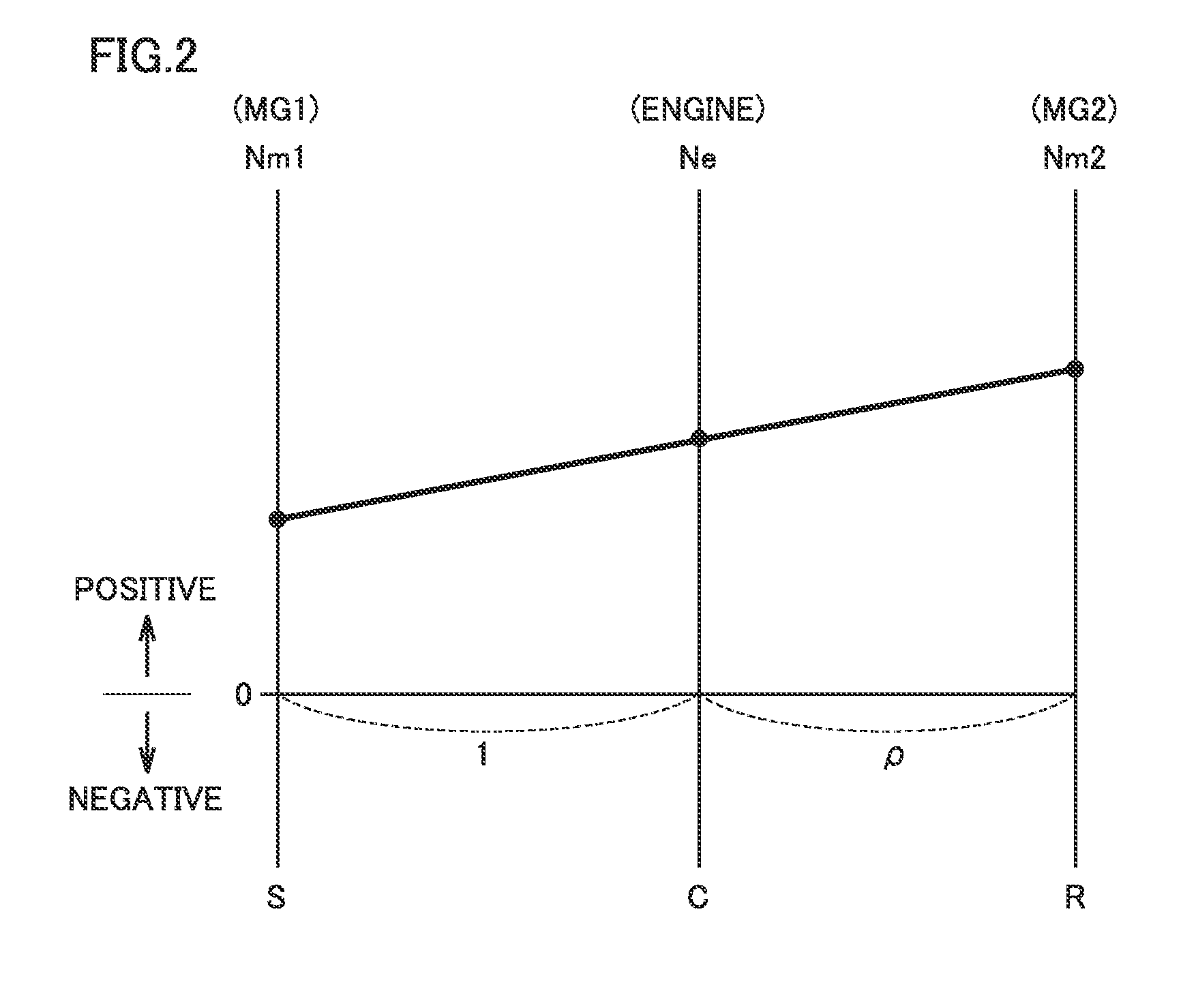
[0128]However, when engine rotation speed Ne remains at a high value by restricting the function of the engine F / B control, first MG rotation speed Nm1 may also remain at a high value based on the relation on the nomographic chart of power split device 300. When first MG rotation speed Nm1 is high, it is concerned that the control mode of first MG 200 becomes the rectangular wave control mode that is inferior in control accuracy to the PWM control mode (see FIG. 5 described above), and the first MG generation power cannot be accurately matched with the second MG discharge power, which leads to a break of the power balance.

[0129]Thus, in a third embodiment, based on whether or not the control ...


PUM


Abstract

A vehicle includes an engine, a first MG (motor generator), a second MG, a planetary gear mechanism provided among the engine, the first MG and the second MG, a battery, and an ECU. The ECU executes batteryless travel control when the battery is abnormal. The batteryless travel control includes engine F/B control for controlling a rotation speed of the engine to become a target rotation speed, and power balance control for controlling a requested driving force to be output and allowing a power generated by the first MG to become equal to a power discharged by the second MG. When the rotation speed of the engine is higher than a threshold speed higher by a prescribed value than the target rotation speed while the batteryless travel control is in execution, the ECU decreases the requested driving force.

Description

CROSS-REFERENCE TO RELATED APPLICATIONS[0001]This application claims priority to Japanese Patent Application No. 2015-156854 filed on Aug. 7, 2015, the entire contents of which are hereby incorporated by reference.BACKGROUND[0002]Field[0003]The present disclosure relates to a driving device for a vehicle, and particularly to a driving device for a vehicle that travels by using at least one of the motive power of an engine and the motive power of a rotating electric machine (motor generator).[0004]Description of the Background Art[0005]Japanese Patent Laying-Open No. 2013-103514 discloses a hybrid vehicle including: an engine; a first rotating electric machine; a second rotating electric machine connected to a driving wheel; a planetary gear mechanism connecting the engine, the first rotating electric machine and the second rotating electric machine; and a battery configured to be connectable to the first rotating electric machine and the second rotating electric machine, wherein the...

Claims


Application Information

Patent Timeline
Patent Type & Authority Applications(United States)
IPC IPC(8): B60W20/50B60W10/08B60L15/08B60K6/365B60K6/448B60L11/08B60W10/06B60K6/40B60L50/13B60L50/16
CPCB60W20/50B60Y2306/13B60W10/08B60K6/40B60K6/365B60K6/448B60L11/08B60L15/08B60W2050/0095B60W2710/0644B60W2710/086Y10S903/93Y10S903/91Y10S903/951B60Y2200/92B60Y2300/188B60Y2300/182B60W10/06B60K6/445B60L2240/421B60L2240/423B60L2240/441B60L2240/443B60L2250/26B60W2050/0008B60W2050/0295B60W2510/0638B60L50/13B60L50/15Y02T10/62Y02T10/64Y02T10/70Y02T10/7072
Inventor TAKUDA, NORITAKA
Owner TOYOTA JIDOSHA KK
Why Eureka
Try Eureka