Annular groove machining cutter tool used for vertical drilling machine

A technology for processing cutting tools and ring grooves, which is applied in the direction of manufacturing tools, metal processing equipment, milling cutters, etc., can solve the problems of inconsistent depth and dimension, long adjustment time, and difficult clamping of workpieces, etc., to achieve good size consistency and production The effect of improving efficiency and easy quality assurance

Inactive Publication Date: 2011-11-23
TIANJIN TIANDA YINTAI RAPID MFG PRODIVITY PROMOTION CENT
View PDF5 Cites 3 Cited by
  • Summary
  • Abstract
  • Description
  • Claims
  • Application Information

AI Technical Summary

Problems solved by technology

There are the following technical problems in lathe machining of the sealing ring groove: 1) the depth of the ring groove is not easy to control, and the depth dimension of the ring groove is often unqualified, resulting in the scrapping of the entire hydraulic valve plate, thereby reducing the yield of the hydraulic valve plate; 2) Machining sealing ring grooves of hydraulic valves on a lathe is difficult and takes a long time to install the workpiece; 3) The depth of the ring groove is greatly affected by the thickness of the ring, which may easily cause inconsistent depth dimensions
It takes a long time to adjust the plate, resulting in low processing efficiency; 4) Machining the sealing ring groove of the hydraulic valve plate on the lathe requires a high-level technician to grind the tool, which requires a high technical level of the technician; 5) Machining sealing ring grooves of hydraulic valves on a lathe is labor-intensive and low in production efficiency

Method used


Image

  • Annular groove machining cutter tool used for vertical drilling machine
  • Annular groove machining cutter tool used for vertical drilling machine
  • Annular groove machining cutter tool used for vertical drilling machine

Examples


Embodiment Construction

[0017] In order to further understand the invention content, characteristics and effects of the present invention, the following examples are given, and detailed descriptions are as follows in conjunction with the accompanying drawings:

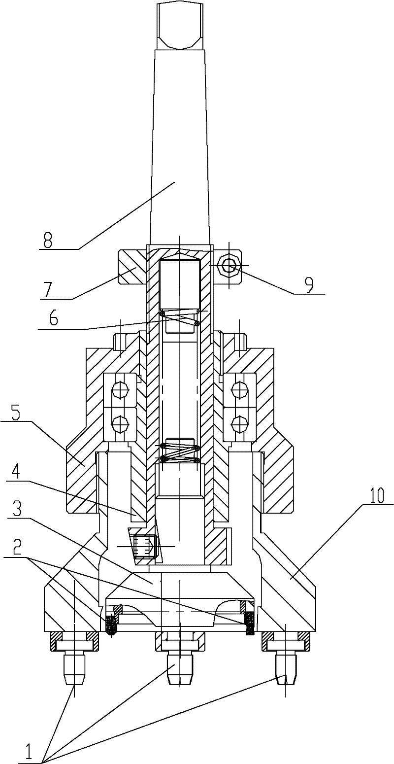
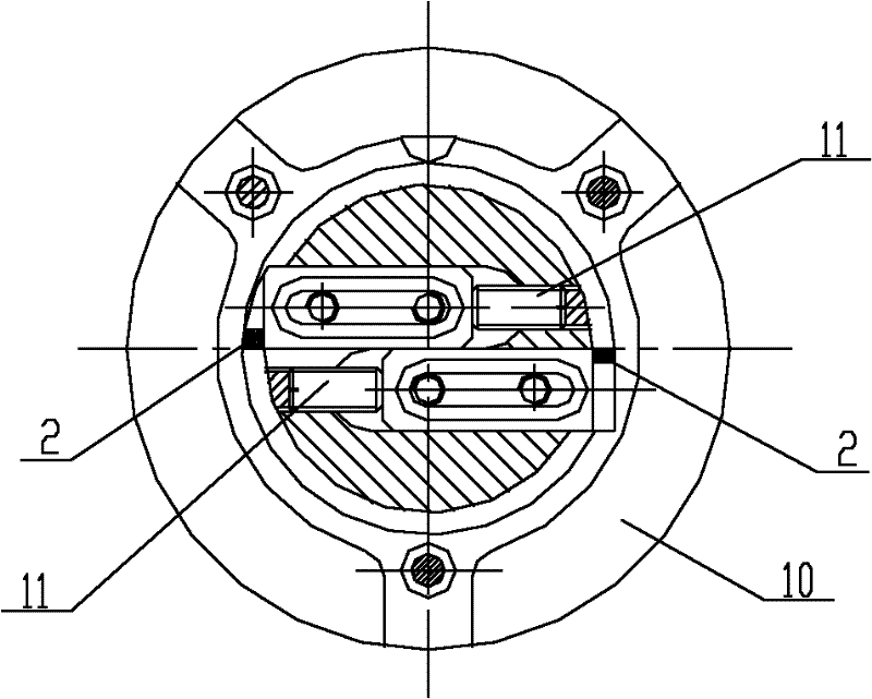
[0018] see Figure 1 ~ Figure 2 , a ring groove processing tool for vertical drilling, including a tool bar 8, the middle part of the tool bar 8 is threaded with a limit lock nut 7, and the lower part of the tool bar 8 is threaded with a mandrel sleeve 4, the The bottom of the cutter bar 8 is equipped with a cutter head 3, on which symmetrically arranged chamfering and grooving cutter heads 2 are arranged; the top of the cutter head 3 is provided with a compression spring installed in the center hole of the cutter bar 6. The outer circle of the mandrel sleeve 4 is supported by a bearing 5 , the bottom of the outer sleeve 5 is fixedly connected with a three-jaw positioning sleeve 10 , and the bottom of the three-jaw positioning sleeve 10 is pr...


PUM


Abstract

The invention discloses an annular groove machining cutter tool used for a vertical drilling machine, comprising a cutter bar, wherein a limiting locknut is connected in the middle of the cutter bar; a spindle sleeve is fixedly connected at the lower part of the cutter bar; a cutter disc is installed at the bottom of the cutter bar; cutter bits arranged symmetrically are installed at the bottom of the cutter disc; an outer sleeve is supported on an excircle of the spindle sleeve through a bearing; and three claw locating sleeves are fixedly connected at the bottom of the outer sleeve. By adopting the annular groove machining cutter tool, machining of annular grooves of six sizes can be completed in one step, the sizes are favorable in consistency, and the precision is easy to control; a processed part is convenient to replace, and the auxiliary time of replacing the processed part is short; the annular groove machining cutter tool is located conveniently and accurately; the groove depth is not influenced by the overall thickness of a hydraulic valve plate; the labor intensity is low and the production efficiency is high. Compared with the annular groove machined on a lathe, the annular groove has the quality which is easily ensured and the production efficiency which can be improved by 2-3 times.

Description

technical field [0001] The invention relates to a tool for processing ring grooves, in particular to a tool for processing ring grooves for vertical drills. Background technique [0002] At present, the sealing ring grooves of hydraulic valve plates are usually processed by lathes. There are the following technical problems in lathe machining of the sealing ring groove: 1) the depth of the ring groove is not easy to control, and the depth dimension of the ring groove is often unqualified, resulting in the scrapping of the entire hydraulic valve plate, thereby reducing the yield of the hydraulic valve plate; 2) Machining sealing ring grooves of hydraulic valve plates on a lathe is difficult and takes a long time to clamp the workpiece; 3) The depth of the ring groove is greatly affected by the thickness of the plate, which may easily cause inconsistent depth dimensions. It takes a long time to adjust the plate, resulting in low processing efficiency; 4) Machining the sealing...

Claims


Application Information

Patent Timeline
Patent Type & Authority Applications(China)
IPC IPC(8): B23C5/10B23C3/28B23C9/00
Inventor 崔爱红曹振起陈光辉宋锐志高博
Owner TIANJIN TIANDA YINTAI RAPID MFG PRODIVITY PROMOTION CENT
Why Eureka
Try Eureka