
Omnibearing automatic welding device

An automatic welding, all-round technology, applied in welding equipment, arc welding equipment, metal processing equipment, etc., can solve the problems of non-dense connection, underfill, undercut, etc., and achieve the effect of improving welding speed and quality

Inactive Publication Date: 2011-11-23
李其明
View PDF3 Cites 0 Cited by
  • Summary
  • Abstract
  • Description
  • Claims
  • Application Information

AI Technical Summary

Problems solved by technology

[0002] At present, in the welding of some small workpieces, manual welding or carbon dioxide gas shielded welding is used, and some weldments often need to be rotated to be completely welded, so that incomplete penetration, undercut, burn-through, and unfilled weldments often occur during welding. Full, not dense or poor connection, and some large-scale welding equipment is often expensive and cumbersome to use, which cannot solve the welding quality and efficiency problems of some small parts

Method used


Image

  • Omnibearing automatic welding device
  • Omnibearing automatic welding device
  • Omnibearing automatic welding device

Examples


specific Embodiment 1

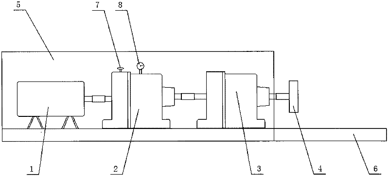
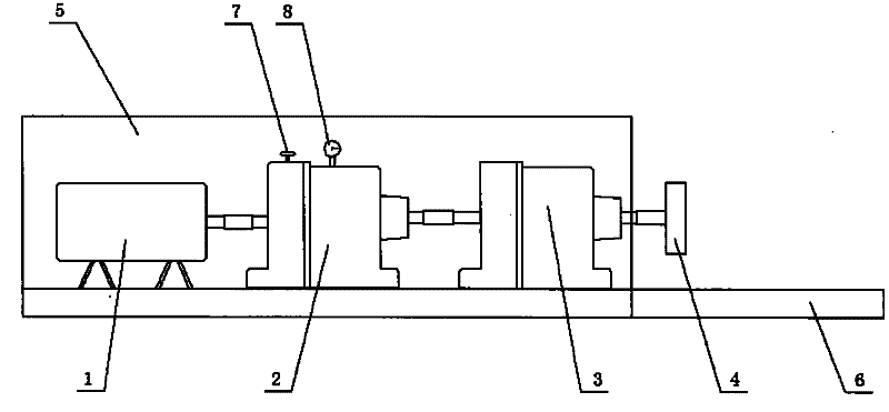
[0013] An all-round automatic welding equipment, including a motor 1, a transmission shaft, a gear-type adjustable reducer 2, and a turbine-type speed-adjustable reducer 3. One end of the motor 1 is connected with a power switch, and the motor 1 is connected to the gear-type adjustable reducer through the connecting shaft. The adjustable speed reducer 2 is connected; the gear type adjustable speed reducer 2 is connected to the turbine type speed control reducer 3, its speed is 20-800r / min, and there is a fixture 4 behind the turbine type speed control reducer 3, the connection method for horizontal connections;

[0014] A rectangular workbench 5 is provided outside the motor 1, the gear-type reducer 2 and the turbine-type speed-regulating reducer 3, and the motor 1, the gear-type adjustable reducer 2, and the turbine-type speed-regulating reducer 3 are arranged inside the workbench 5, Protect the safety of the machine and staff; there is a protruding table at the bottom of the...

specific Embodiment 2

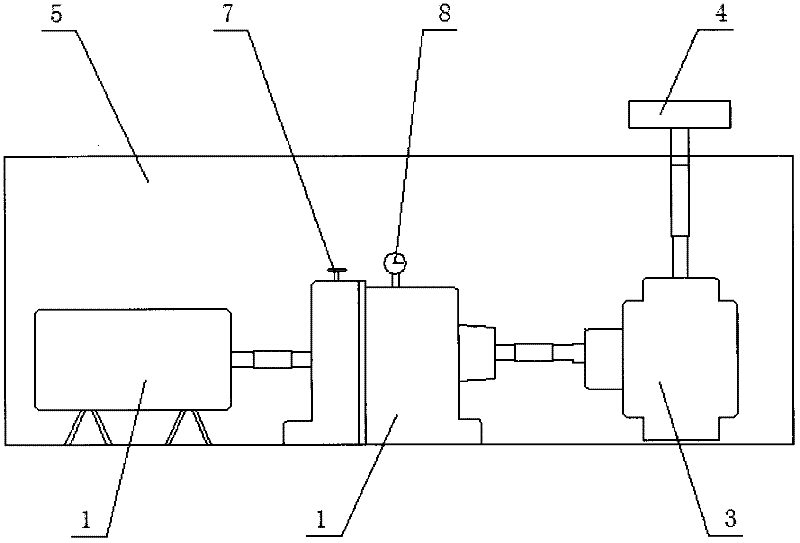
[0017] An all-round automatic welding equipment, including a motor 1, a transmission shaft, a gear-type adjustable reducer 2, and a turbine-type speed-adjustable reducer 3. One end of the motor 1 is connected with a power switch, and the motor 1 is connected to the gear-type adjustable reducer through the drive shaft. The adjustable speed reducer 2 is connected; the gear type adjustable speed reducer 2 is connected to the turbine type speed control reducer 3, its speed is 20-800r / min, and there is a fixture 4 behind the turbine type speed control reducer 3, the connection method for vertical connection;

[0018] There is a rectangular workbench 5 outside the motor 1, the gear-type adjustable reducer 2 and the turbine-type speed-adjustable reducer 3, and the motor 1, the gear-type adjustable reducer 2, and the turbine-type speed-adjustable reducer 3 are arranged on the workbench 5 Inside, it protects the safety of the machine and workers; the top of the rectangular workbench is...


PUM


Abstract

The invention discloses an omnibearing automatic welding device which comprises a motor, a transmission shaft, a gear-type adjustable reducer and a turbo-type speed-adjusting reducer, wherein one end of the motor is connected with a power switch, the motor is connected with the gear-type adjustable reducer through a connecting shaft; the turbo-type speed-adjusting reducer is connected behind the gear-type adjustable reducer, a fixture is connected behind the turbo-type speed-adjusting reducer; and a workbench is externally connected with the motor, the gear-type reducer and the turbo-type speed-adjusting reducer. The invention has the advantages that the welding device is suitable for welding in the horizontal direction and the vertical direction, is especially suitable for welding round weldments, and greatly improves the welding speed and quality.

Description

technical field [0001] The invention designs a welding equipment, in particular relates to an all-round automatic welding equipment. Background technique [0002] At present, in the welding of some small workpieces, manual welding or carbon dioxide gas shielded welding is used, and some weldments often need to be rotated to be completely welded, so that incomplete penetration, undercut, burn-through, and unfilled weldments often occur during welding. Full, not dense or poor connection, and some large-scale welding equipment is often expensive and cumbersome to use, which cannot solve the welding quality and efficiency problems of some small parts. Contents of the invention [0003] In order to overcome the above-mentioned problems, the present invention provides a kind of welding equipment with simple structure and convenient operation. The technical scheme adopted is as follows: [0004] An all-round automatic welding equipment, including a motor, a transmission shaft, a...

Claims


Application Information

Patent Timeline
IPC IPC(8): B23K9/12B23K9/16
Inventor 李其明
Owner 李其明
Learn More