Biomass particle molding module and biomass particle molding machine

A biomass granule and granule molding technology, which is applied in the direction of material forming presses, mold extrusion granulation, presses, etc., can solve the problems that affect the production of biomass granules and the difficulty of entering biomass materials, and achieve increased extrusion Pressure and anti-slip ability, avoid slipping effect

Inactive Publication Date: 2011-11-23
YIWU ANDONG ELECTRICAL APPLIANCES
View PDF5 Cites 25 Cited by
  • Summary
  • Abstract
  • Description
  • Claims
  • Application Information

AI Technical Summary

Problems solved by technology

[0003] Through the above working process, we can see that during the extrusion process of the above-mentioned pressure roller and ring die, since the pressing surface of the pressure roller and ring die is flat, it is inevitable tha

Method used


Image

  • Biomass particle molding module and biomass particle molding machine
  • Biomass particle molding module and biomass particle molding machine
  • Biomass particle molding module and biomass particle molding machine

Examples


Embodiment 1

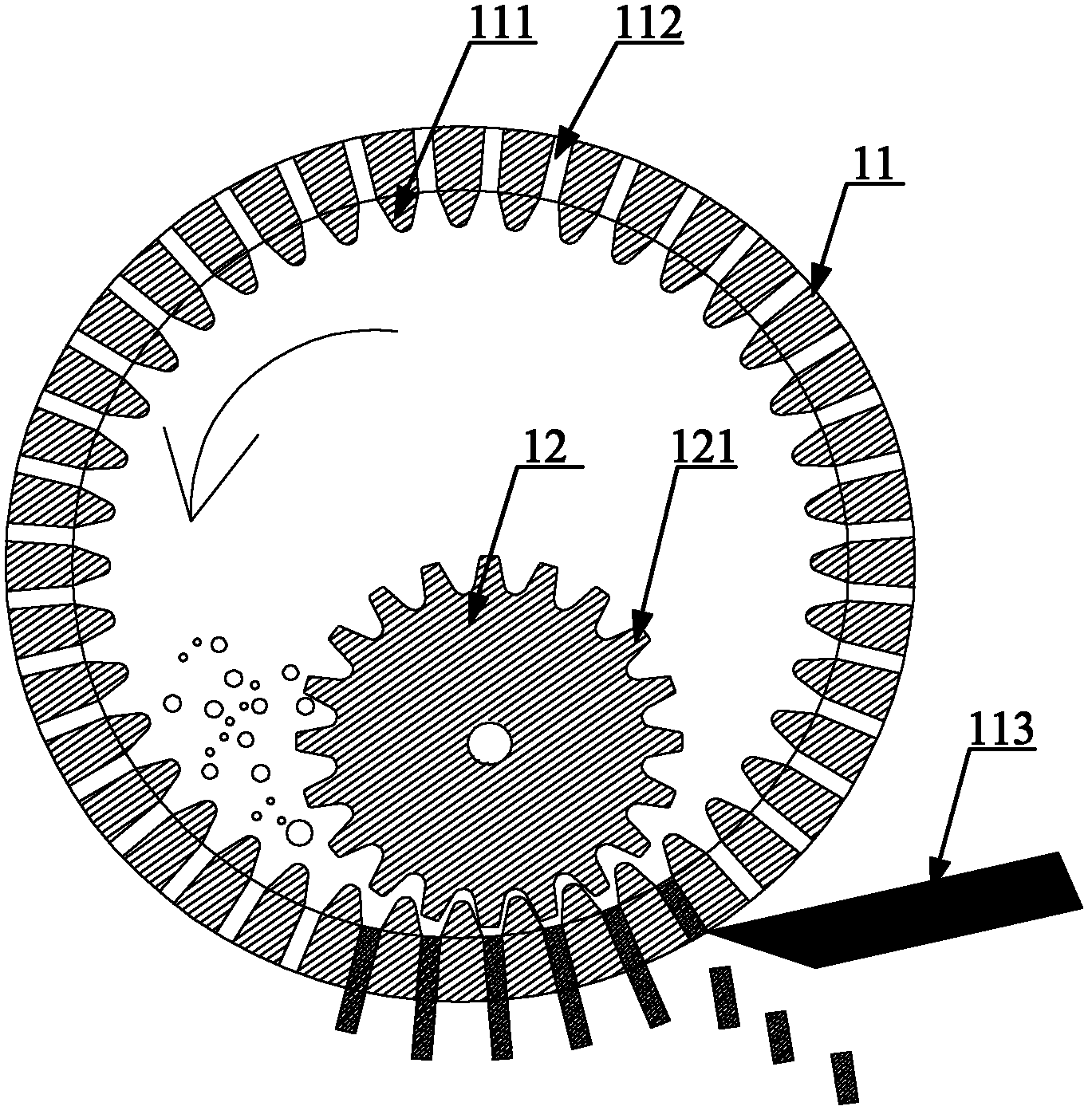
[0028] Please refer to the attached figure 1 , figure 1 It is a schematic structural diagram of the biomass particle forming module provided in Embodiment 1 of the present invention.

[0029] The biomass particle molding module provided in this embodiment includes a ring die 11 and a pressing roller 12, wherein the ring die 11 is provided with a particle forming hole 112, and the pressing surface of the ring die is provided with ring die meshing teeth 111, and the pressing roller 12 The pressing surface of the ring die meshing teeth 111 is provided with a pressure roller meshing tooth 121, and the particle forming hole 112 is located between two adjacent ring die meshing teeth 111, wherein: the ring die meshing tooth 111 is set on the ring On the inner wall of the mold 11, the pressure roller 12 is located inside the ring mold 11, and the engagement teeth 111 of the ring mold and the engagement teeth 121 of the pressure roller are engaged in an inscribed engagement.

[0030]...

Embodiment 2

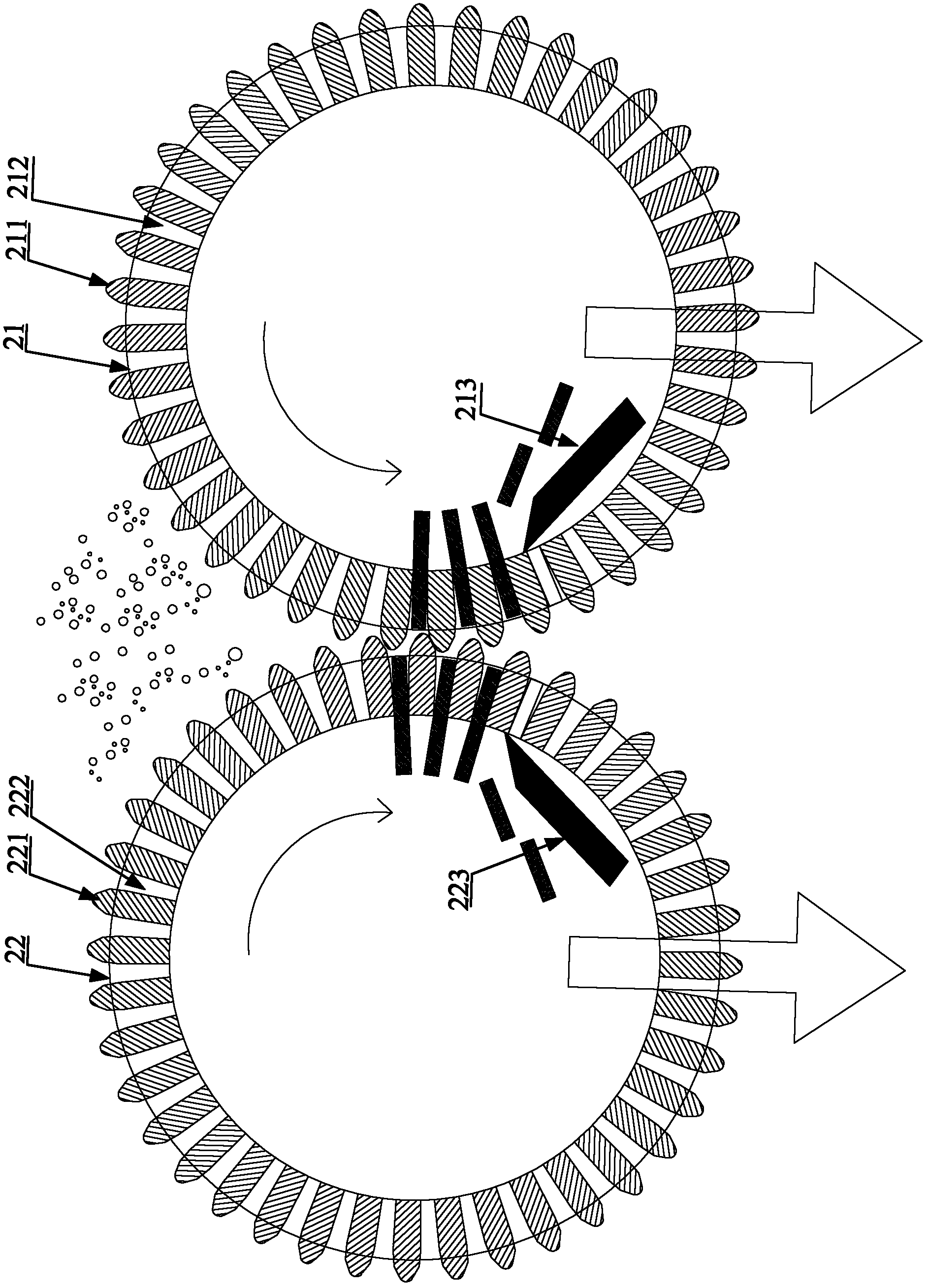
[0034] Please refer to the attached figure 2 , figure 2 It is a schematic structural diagram of the biomass particle forming module provided by the second embodiment of the present invention.

[0035] The biomass particle forming module provided in this embodiment includes a ring die 21 and a pressure roller, wherein the ring die 21 is provided with a particle forming hole 212, and the pressing surface of the ring die 21 is provided with a ring die meshing tooth 211, and the pressure roller On the pressing surface, there are pressure roller meshing teeth that mesh with the ring die meshing teeth 211, and the particle forming hole 212 is located between two adjacent ring die meshing teeth 211, wherein: the ring die meshing teeth 211 are set on the ring die 21 On the outer wall of the ring die 21, the pressing roller is located outside the ring die 21, and the ring die meshing teeth 211 and the pressing roller meshing teeth are circumscribed and meshed.

[0036] The working ...

Embodiment 3

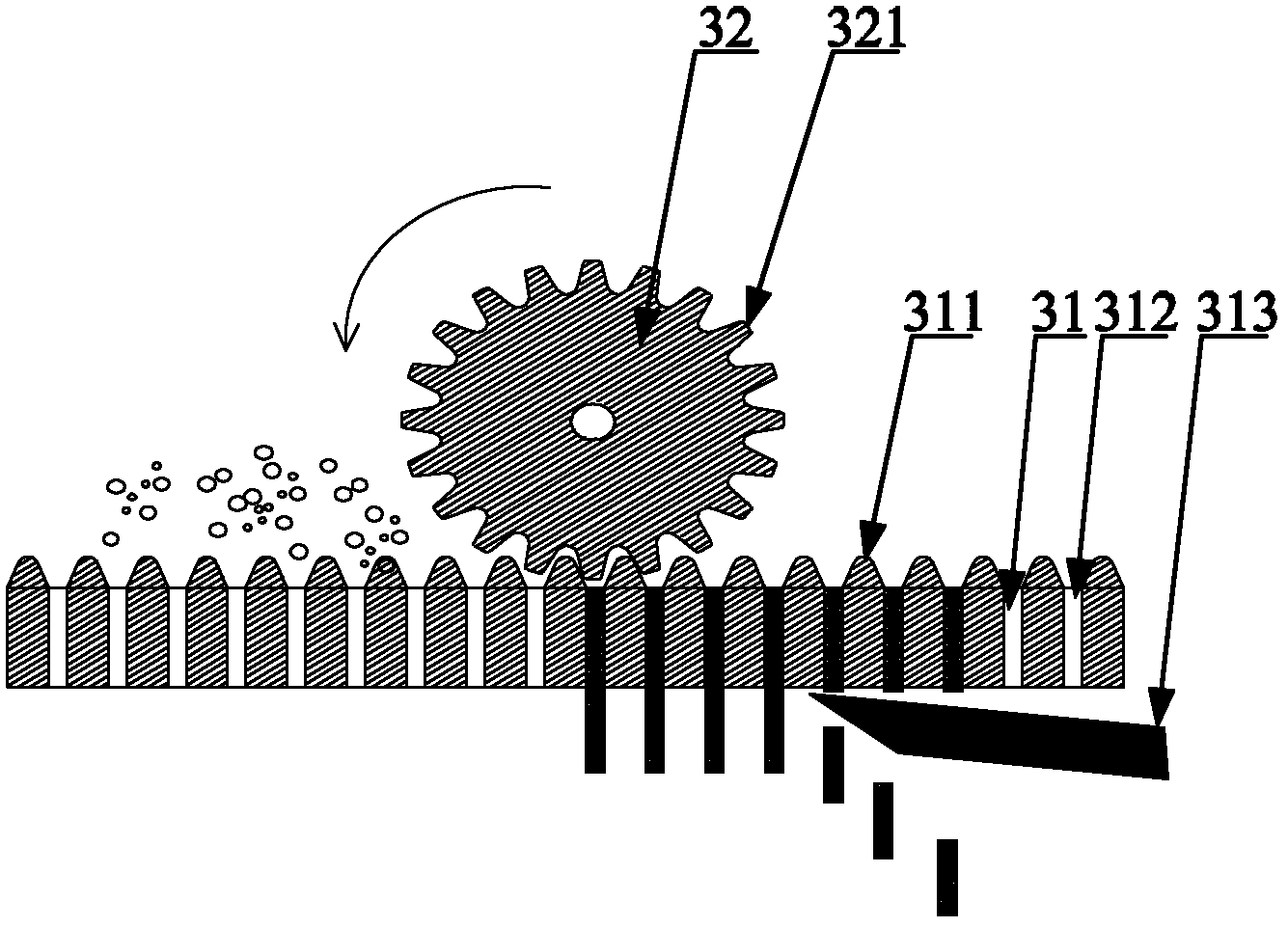
[0040] Please refer to the attached Figure 3-4 , image 3 Schematic diagram of the structure of the biomass particle forming module provided by Embodiment 3 of the present invention; Figure 4 for image 3 Schematic diagram of the top view structure.

[0041] The biomass particle molding module provided in this embodiment includes a ring die 31 and a pressing roller 32, wherein the ring die 31 is provided with a particle forming hole 312, and the pressing surface of the ring die 31 is provided with ring die meshing teeth 311, and the pressing roller 32 is provided with a pressure roller meshing tooth 321 that meshes with the ring die meshing tooth 311, and the particle forming hole 312 is located between two adjacent ring die meshing teeth 311, wherein: the ring die meshing tooth 311 is arranged on On the outer wall of the ring die 31, the pressure roller 32 is located outside the ring die 31, and the engagement of the ring die meshing teeth 311 and the pressure roller mes...


PUM


Abstract

The invention provides a biomass particle molding module comprising a ring mold and a press roll, wherein particle molding holes are formed on the ring mold; ring mold engaging teeth are arranged on a pressing fit surface of the ring mold; press roll engaging teeth engaged with the ring mold engaging teeth are arranged on a pressing fit surface of the press roll; and the particle molding holes are positioned between the two adjacent ring mold engaging teeth. In the biomass particle molding module provided by the invention, the slipping phenomenon between the ring mold and the press roll in the material extruding process is avoided through the engaging fit between the ring mold engaging teeth and the press roll engaging teeth. The invention also provides a biomass particle molding machine on which the biomass particle molding module is arranged.

Description

technical field [0001] The present invention relates to the technical field of biomass particle manufacturing equipment, and more specifically, relates to a biomass particle forming module, and the present invention also relates to a biomass particle forming machine having the above-mentioned biomass particle forming module. Background technique [0002] The existing biomass forming module includes a pressing roller and a ring die, and the pressing surface of the ring die is a plane structure, and forming holes are arranged on it. During the working process, the pressure roller and the ring die rotate, and the material enters the gap between the two. The material is squeezed by the pressure roller and the ring die, and finally is extruded from the forming hole on the ring die, and is set in the ring. The cutter on the extrusion end of the forming hole on the mold cuts off, thus realizing the production of biomass pellets. [0003] Through the above working process, we can s...

Claims


Application Information

Patent Timeline
IPC IPC(8): B30B11/20B01J2/22
CPCB30B11/228B30B11/201B30B11/227B30B11/28
Inventor 陈前喜朱宏锋
Owner YIWU ANDONG ELECTRICAL APPLIANCES
Why Eureka
Try Eureka