
Combined type greening barrier

A combined, isolation fence technology, applied in the field of isolation fences, can solve the problems of wide land occupation, complex guardrail structure, endangering life safety, etc.

Active Publication Date: 2011-11-23
孙希贤
View PDF9 Cites 5 Cited by
  • Summary
  • Abstract
  • Description
  • Claims
  • Application Information

AI Technical Summary

Problems solved by technology

[0002] The support of Chinese patent CN2542716 is exactly guardrail or isolation fence, and it adopts on the support of patent application number 02220331.1 on the guardrail or isolation barrier that itself does not have greening, and planter is installed on the guardrail or flower stand with fixed connector, and then flowers and plants are planted On the planter, the result is that the planter makes the steel structure guardrail or flower stand too large in size and load, so that the guardrail produces a turning moment without safety and stability, that is, it is top-heavy and easy to tip over and collapse, and it occupies a wide area, and the external irrigation pipe It makes the guardrail structure complex, unattractive and high in cost. What's more, the additional external flower troughs and irrigation pipes seriously endanger the safety of road traffic and pedestrians. If this technology is applied to high-rise buildings, it is very easy to be Wind-blown fall endangers human life

Method used


Image

  • Combined type greening barrier
  • Combined type greening barrier
  • Combined type greening barrier

Examples


Embodiment 1

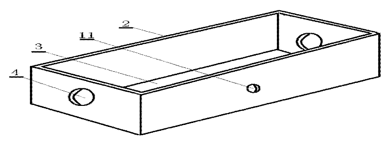
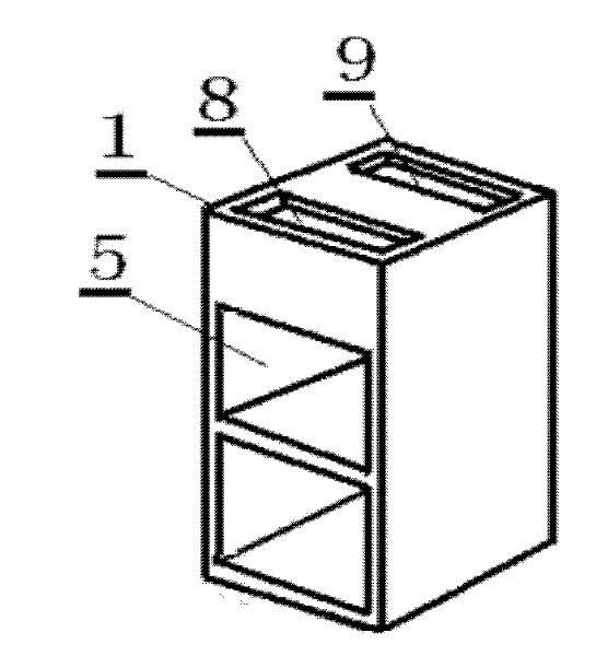
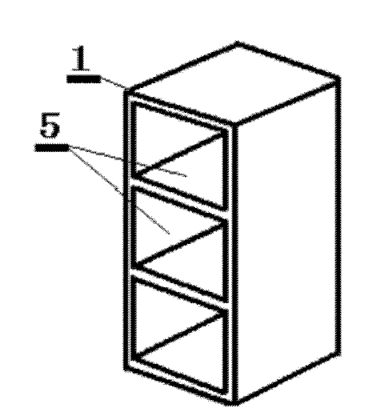
[0055] Embodiment 1: as figure 1 , figure 2 , Figure 4 , as an embodiment 1 of this example, the combined green fence includes a support 1 and a transverse isolation bar 2, which is characterized in that: the outlines of the support 1 and the transverse isolation bar 2 are both front-back and left-right symmetry structure, the upper part of the horizontal isolation bar 2 is the planting space, the lower part is the reservoir and the water channel 3, the left and right ends of the horizontal isolation bar 2 have corresponding water supply and drainage holes 4, and the support 1 has a side to the The through hole 5 on the other side, the vertical symmetry plane of the through hole 5 is parallel to the vertical symmetry plane of the support 1 and the distance is within 6 cm, and any section of the entire outer surface of the horizontal spacer bar 2 is surrounded by the support 1 through hole 5 and overhead splicing, its support 1 can be spliced ​​and moved arbitrarily on the ...

Embodiment 2

[0064] Embodiment 2: as Image 6 , Figure 7 , Figure 8 , as an embodiment 1 of this example, the combined green fence includes a support 1 and a transverse isolation bar 2, which is characterized in that: the outlines of the support 1 and the transverse isolation bar 2 are both front-back and left-right symmetry Structure, the upper part of the horizontal spacer bar 2 is the planting space, the lower part is the reservoir and the water flow channel 3, the two symmetrical outer ends of the transverse spacer bar 2 have straight-through pipes 6 for splicing and water flow corresponding to the position, and the support 1. There are straight through holes 7 for splicing and support and through grooves 12 concaved on the top surface from one side to the other side, and the vertical holes 7 for splicing and supporting or the through grooves 12 concaved on the top face are vertical. The plane of symmetry is parallel to the vertical plane of symmetry of the support 1 and the distan...

Embodiment 3

[0074] Embodiment 3: as Figure 15 , Figure 16 , Figure 17, as an embodiment 1 of this example, the combined green fence includes a support 1 and a transverse isolation bar 2, which is characterized in that: the outlines of the support 1 and the transverse isolation bar 2 are both front-back and left-right symmetry structure, the upper part of the horizontal isolation bar 2 is the planting space, the lower part is the reservoir and the water channel 3, the left and right ends of the horizontal isolation bar 2 have corresponding water supply and drainage holes 4, and the support 1 has a side to the The other side has a straight-through hole 7 for splicing and support, the vertical symmetry plane of the through-hole 7 for splicing and support is parallel to the vertical symmetry plane of the support 1 and the distance is within 6 centimeters, and the transverse spacer bar 2 passes through Bolts or hollow pipe bolts pass through the through hole 7 of the support 1 for splicin...


PUM


Abstract

The invention discloses a combined type greening barrier. The combined type greening barrier comprises supports and horizontal spacer bars and is characterized in that the profiles of the supports and the horizontal spacer bars are of a fore-and-aft and bilateral symmetry structure, a planting space is arranged at the upper parts of the horizontal spacer bars, a water reservoir also serving as a flowing channel is arranged at the lower parts of the horizontal spacer bars, water supplying and draining holes also serving as connection holes which correspond to one another in positions are arranged on the left end surfaces and right end surfaces of the horizontal spacer bars, each support is provided with a through hole from one side surface to the other side surface, any one section of the whole outer surface of each horizontal spacer bar is enclosed in the through hole of each support and spliced in a suspension manner, the supports can be randomly spliced and moved on the whole outer surface of the horizontal spacer bar, the end surfaces of the adjacent horizontal spacer bars are connected in series directly by virtue of the water supplying and draining holes also serving as the connection holes or indirectly through bolts or hollow pipe bolts with a plastic sealing pad, the water reservoir also serving as the flowing channel at the lower parts of the horizontal spacer bars is penetrated to form a combined greening barrier; and a part between any two adjacent supports and the horizontal spacer bars in the combined greening barrier is of a symmetrical structure.

Description

technical field [0001] The invention relates to an isolation fence, in particular to a combined green isolation fence in which plants are planted or flower pots are placed. Background technique [0002] The support of Chinese patent CN2542716 is exactly guardrail or isolation fence, and it adopts on the support of patent application number 02220331.1 on the guardrail or isolation barrier that itself does not have greening, and planter is installed on the guardrail or flower stand with fixed connector, and then flowers and plants are planted On the planter, the result is that the planter makes the steel structure guardrail or flower stand too large in size and load, so that the guardrail produces a turning moment without safety and stability, that is, it is top-heavy and easy to tip over and collapse, and it occupies a wide area, and the external irrigation pipe The structure of the guardrail is complex, unattractive and costly. More importantly, the additional external plant...

Claims


Application Information

Patent Timeline
IPC IPC(8): E04H17/14E04F11/18E01F15/02A01G9/02A01G27/02
CPCE01F8/022
Inventor 孙希贤
Owner 孙希贤
Learn More