Mounting structure of disc hob

A disc-shaped hob and installation structure technology, applied in mining equipment, earth-moving drilling, tunnels, etc., can solve problems such as disadvantage, low installation efficiency, complicated loading and unloading process, etc., to improve the efficiency of replacement, simplify the installation method, install Convenient and fast effects

Inactive Publication Date: 2011-11-23
TIANJIN UNIV
View PDF8 Cites 31 Cited by
  • Summary
  • Abstract
  • Description
  • Claims
  • Application Information

AI Technical Summary

Problems solved by technology

The embedded method generally uses bolts to fix the hob shaft, which makes the installation and disassembly process of the hob complicated, and must be replaced one by one by workers. The installation efficiency is low, which is not conducive to the implementation of mechanical automation in the future

Method used


Image

  • Mounting structure of disc hob
  • Mounting structure of disc hob
  • Mounting structure of disc hob

Examples


Embodiment Construction

[0024] The present invention will be further described in detail below in combination with specific embodiments.

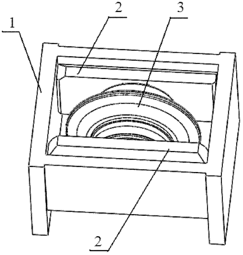
[0025] like figure 1 As shown, a disc-shaped hob installation structure of the present invention includes a hob shaft supporting frame 1 , a hob shaft seat 2 and a fixed cover plate 7 .

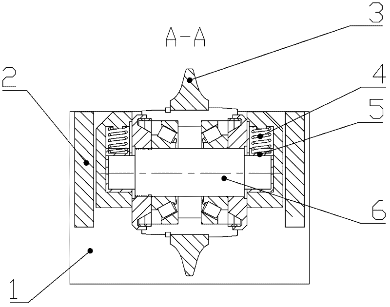
[0026] like Figure 8-1 and Figure 8-2 As shown, the two shaft ends of the hob central shaft 6 are milled and flattened to form a flat shaft head. There is an included angle of 3-20 degrees between the opposite sides of the cross section of each flat shaft head. Among the two relative arc surfaces, the radian of one arc surface is greater than that of the opposite arc surface; that is, the two shaft ends of the central axis 6 of the hob are cut into a flat shaft head shape with a bevel.

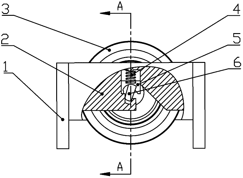
[0027] like Figure 4 As shown, the hob shaft support frame is a rectangular frame, and the inner sides of the two opposite side vertical plates of the hob shaft support frame 1 are respect...


PUM


Abstract

The invention discloses a mounting structure of a disc hob, which comprises a hob shaft support frame, hob shaft bases and a fixed cover plate. Two shaft ends of a hob center shaft are both processed by flat milling to form a flat shaft head with an inclined surface. The hob shaft support frame is a rectangular frame, the inner sides of the two opposite side upright plates of the hob shaft support frame are respectively fixedly provided with one hob shaft base in a connecting manner, an open groove is arranged on the inner side surface of each hob shaft base from bottom to top, a pressure spring, a limit slider and a trapezoid shaft base groove are arranged in the open groove from top to bottom, the bottom of the limit slider is an arc surface with a concave bottom, and a shaft base hole is formed between the arc surface with a concave top and the trapezoid shaft base groove. The side below the open groove is provided with an inclined surface, and an inclined channel is formed from the inclined surface to the opening. The flat shaft head of the disc hob center shaft is matched with the shaft base hole. According to the invention, the disc hob can be conveniently and quickly mounted, and space is widened for the further application of an automation technology. The invention has good application prospects.

Description

technical field [0001] The invention relates to a shield machine part for tunnel construction, in particular to an installation structure of a shield machine hob on a knife seat. Background technique [0002] At present, more and more shield machines are used for underground excavation in underground engineering, while full-face hard rock excavators are more commonly used for hard rock excavation. As an efficient excavating tool, the hob is widely used in the above two excavating equipment, especially for hard rock excavation, it is already an indispensable excavating tool. During the excavation process of the shield machine and the hard rock excavator, as the cutter head rotates continuously, the hob installed on the cutter head will continue to roll the rock. This long-term interaction between them will cause continuous wear of the hob, so that when the wear of the hob reaches a certain level, the efficiency of cutting rocks will be reduced, the original excavation effect...

Claims


Application Information

Patent Timeline
Patent Type & Authority Applications(China)
IPC IPC(8): E21D9/087
Inventor 蒋聪健郭伟刘建琴朱殿华蒲毅
Owner TIANJIN UNIV
Why Eureka
Try Eureka