High pressure valve and control method

A technology for high-pressure valves and valve seats, applied in valve details, valve devices, valve operation/release devices, etc., can solve problems such as large energy consumption, and achieve the effect of avoiding thermal expansion coefficient

Inactive Publication Date: 2011-11-23
SHENZHEN MINDRAY BIO MEDICAL ELECTRONICS CO LTD
View PDF4 Cites 2 Cited by
  • Summary
  • Abstract
  • Description
  • Claims
  • Application Information

AI Technical Summary

Problems solved by technology

As a result, large, strong, expensive and power-hungry electromagnets are a must in this design

Method used


Image

  • High pressure valve and control method
  • High pressure valve and control method

Examples


Embodiment Construction

[0022] The present invention will be further described in detail below through specific embodiments in conjunction with the accompanying drawings.

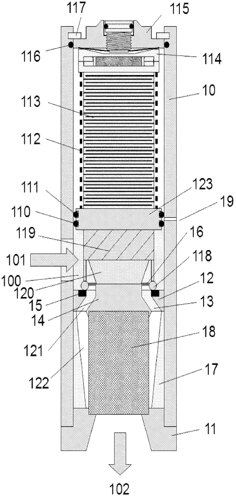
[0023] figure 1 is a schematic diagram of one embodiment of a piezo-controlled high pressure valve, externally comprising a conduit 10 having an inlet conduit 101 , an outlet conduit 102 and a fine adjustment screw 50 on a mechanical fine adjustment element 115 . Inside the pipeline 10 , it includes a mechanical precision adjustment element, a mechanical thermal expansion element 114 , a piezoelectric actuator 113 , a pretensioned pipeline 112 , a buffer disk 123 , a connecting and unloading amplifier 119 , and a valve structure 118 . The valve seat 115 and the flow measuring net 18 surround in series. The mechanical fine adjustment element 115 is secured to the pipe 10 by a spring ring 117 and sealed by a surrounding O-ring 116 . The buffer disk 123 is located between the piezoelectric actuator 113 and the high pressure chamber...


PUM


Abstract

A system and a method are described for converting a small motion from a piezoelectric actuator to a larger motion in a valve mechanism. A piezoelectric actuator is connected in series to a mechanical amplifier, a mechanical temperature compensation element, a mechanical fine tuning element, all acting in the same effective direction as the piezoelectric actuator.

Description

technical field [0001] The present invention relates to piezo-controlled high pressure valves and methods of controlling them, particularly for converting small movements, especially from piezoelectric actuators, into large movements that can control the valve mechanism. Background technique [0002] In the field of piezoceramics, piezoceramic elements are widely used in actuator applications as new technologies develop and replace electromagnetic solutions. The reason is that the forces associated with the intrinsic mass (intrinsic mass) are ten times greater in piezoelectric ceramic technology than in electromagnetic technology. An example is the replacement of electromagnets by piezoelectric actuators in fuel injection valves in the automotive industry. This ushered in an era of car engines with low fuel consumption and low emissions. Thanks to piezoelectric actuator technology, it is possible to control the fuel injection in milliseconds with each piston movement. [...

Claims


Application Information

Patent Timeline
Patent Type & Authority Applications(China)
IPC IPC(8): F02M51/06
CPCF16K31/004
Inventor 戈兰·西维斯
Owner SHENZHEN MINDRAY BIO MEDICAL ELECTRONICS CO LTD
Why Eureka
Try Eureka