Device for drying bulk material in at least one storage container

A technology for storing containers and loose materials. It is used in drying solid materials, drying gas arrangements, and dryers for static materials. It can solve the problems of expensive equipment parts and huge space, and achieve the best dehumidification effect.

Inactive Publication Date: 2011-11-23
MOTAN HLDG
View PDF0 Cites 12 Cited by
  • Summary
  • Abstract
  • Description
  • Claims
  • Application Information

AI Technical Summary

Problems solved by technology

Such refrigeration machines are not only expensive equipment components, but also require huge space

Method used


Image

  • Device for drying bulk material in at least one storage container
  • Device for drying bulk material in at least one storage container
  • Device for drying bulk material in at least one storage container

Examples


Embodiment Construction

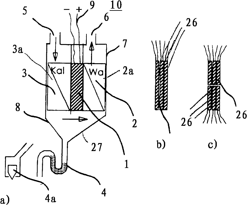
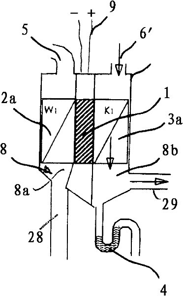
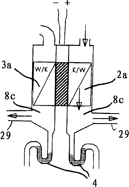
[0026] with the help of Figures 1 to 3 Explain the principle of the device for drying bulk materials according to the invention. The bulk material is dried using a dehumidification unit 10 which has at least one Peltier element. The dehumidification unit 10 has a housing 7 which is divided into two flow chambers 2 , 3 by a partition wall 1 . The partition wall 1 is provided with at least one Peltier element 26 . Such as figure 1 As shown in b and 1c, it can be connected ( figure 1 b) can also be consecutive and side by side ( figure 1 c) A plurality of Peltier elements 26 are arranged. Using several Peltier elements 26 can increase the temperature difference.

[0027] The characteristic of a Peltier element is that when an electric current is applied, one plane is heated and the other side is cooled.

[0028] exist figure 1 In the embodiment shown in a, the cold side of the Peltier element 26 is located in the flow chamber 3 and the hot side is located in the flow cha...


PUM


Abstract

Before being processed, bulk material is dried in a storage container. A drying medium such as air is passed through the bulk material for drying. The drying medium heats the bulk material and removes moisture at the same time. For dehumidifying the drying medium, a dehumidifying unit with a Peltier device is provided whose cold side and whose hot side are positioned within the flow path of the drying medium. The drying medium loaded with moisture is passed across the cold side and dehumidified. The hot side of the Peltier device is used to preheat the dehumidified drying medium.

Description

technical field [0001] The invention relates to a device for drying bulk material in at least one storage container according to the preamble of claim 1 . Background technique [0002] The bulk material is dried in storage containers prior to its processing, for which a drying medium, preferably air, is passed through the bulk material. The drying medium heats the bulk material and absorbs moisture from it at the same time. The drying medium laden with moisture is discharged from the storage container through the outlet pipe. This so-called return air then passes through the drying unit in order to dehumidify the drying medium again and to feed it to the bulk material. In order to remove moisture from the drying medium, a refrigeration machine of a conventional structure is used to cool the drying medium to remove moisture. The hot exhaust air is also partly led to a refrigeration machine in order to reheat the drying medium after the dehumidification process in order to ...

Claims


Application Information

Patent Timeline
Patent Type & Authority Applications(China)
IPC IPC(8): F26B21/08F26B21/10F25B21/04
CPCB01D53/265F26B21/086F26B23/04F26B21/04F26B17/1408F26B2200/08F26B21/083F26B9/06F26B3/04F26B21/02F25B21/02
Inventor H·库瑙R·黑罗
Owner MOTAN HLDG
Why Eureka
Try Eureka