Forward topology synchronous rectification driver circuit

A technology of synchronous rectification and drive circuit, which is applied in the direction of electrical components, adjustment of electric variables, high-efficiency power electronic conversion, etc. It can solve the problems of circuit conversion efficiency reduction, freewheeling tube damage, reset voltage intermittent state, etc., to avoid insufficient drive , Reliable conduction effect

Active Publication Date: 2011-04-27
BEIJING SUPLET +1
View PDF4 Cites 12 Cited by
  • Summary
  • Abstract
  • Description
  • Claims
  • Application Information

AI Technical Summary

Problems solved by technology

In this synchronous rectification drive technology, the drive signal of the freewheeling tube comes from the reset voltage of the reset capacitor. The waveform of the reset voltage is parabolic. When the input voltage is high, the duty ratio of the entire power supply is small, which will cause the reset voltage An intermittent state occurs, which makes the driving voltage on the freewheeling tube close to zero in the latter part of a cycle, resulting in insufficient driving of the freewheeling tube. At this time, the freewheeling current of the inductor will pass through the body diode of the freewheeling tube, which is The main reason for the low conversion efficiency of the power circuit and the damage of the freewheeling tube is also the bottleneck affecting the reliability of the power circuit in the application.
Therefore, when the synchronous rectification drive circuit in the prior art has a large input voltage variation range, the conversion efficiency of the entire circuit is reduced, and the device is easily damaged

Method used


Image

  • Forward topology synchronous rectification driver circuit
  • Forward topology synchronous rectification driver circuit
  • Forward topology synchronous rectification driver circuit

Examples


Embodiment Construction

[0017] In order to make the purpose, technical solutions and advantages of the embodiments of the present invention clearer, the technical solutions in the embodiments of the present invention will be clearly and completely described below in conjunction with the drawings in the embodiments of the present invention. Obviously, the described embodiments It is a part of embodiments of the present invention, but not all embodiments. Based on the embodiments of the present invention, all other embodiments obtained by persons of ordinary skill in the art without making creative efforts belong to the protection scope of the present invention.

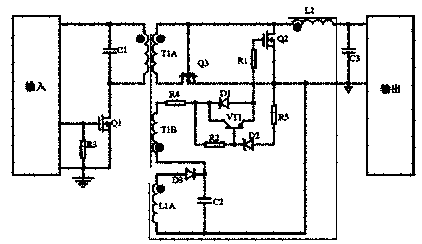
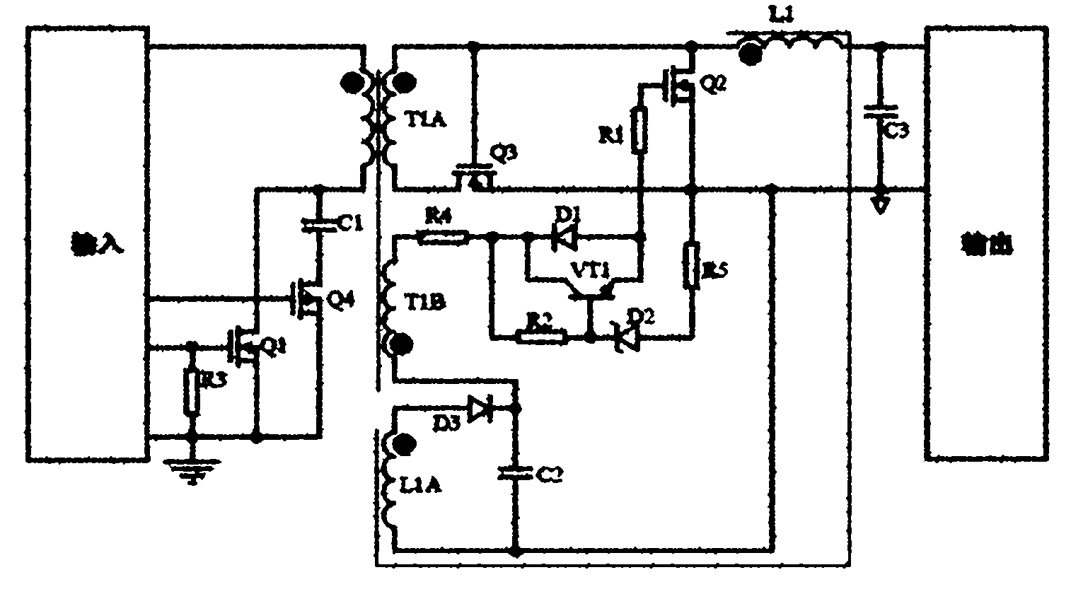
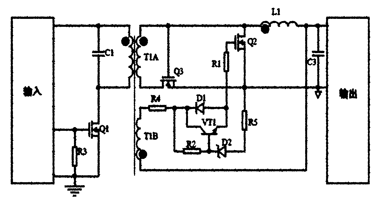
[0018] figure 1 It is a schematic diagram of an embodiment of the forward topology synchronous rectification driving circuit provided by the present invention. Such as figure 1 As shown, in this embodiment, the synchronous rectification driving circuit includes a rectifier tube Q3 connected between the secondary terminal of the transformer ...


PUM


Abstract

The invention provides a forward topology synchronous rectification driver circuit comprising a rectifying tube Q3 and a follow current tube Q2, wherein the rectifying tube Q3 is connected between the secondary-side synonym end of a transformer and ground, and the follow current tube Q2 is connected between the secondary-side homonym end of the transformer and the ground; and an output inductor L1 is connected between the secondary-side homonym end of the transformer and the output end of a circuit. The driver circuit also comprises an auxiliary winding T1B of the transformer, wherein the synonym end of the auxiliary winding T1B of the transformer is connected with the cathode of a diode D1, the collector electrode of a triode VT1 and the public end of the first end of the auxiliary winding T1B of the transformer by a resistor R4; the second end of the resistor R2 is connected with the base electrode of the triode VT1 and the cathode of a stabilivolt D2 of which the anode is earthed by a resistor R5; the anode of the diode D1 is connected with the emission electrode of the triode VT1 and the first end of the resistor R1; the second end of the resistor R1 is connected with the gridelectrode of the follow current tube Q2; and the homonym end of the auxiliary winding T1B of the transformer is connected with the output end of the circuit.

Description

technical field [0001] The invention belongs to the field of DC / DC power supply circuits, in particular to a drive circuit of a forward topology synchronous rectification drive circuit. Background technique [0002] At present, power supplies that output low voltage and high current are more and more widely used in the communication field, which requires higher power conversion efficiency. In order to maintain the high efficiency of power conversion, the secondary side synchronous rectification technology is usually used. [0003] The key in synchronous rectification technology is the drive technology. The most widely used method is self-driven or winding-driven. Among them, the single-ended forward self-driven synchronous rectification topology with capacitor reset is widely used because of its simple circuit, few components, and low cost, especially in the power supply occasions with small and medium power and limited volume. In this synchronous rectification drive tech...

Claims


Application Information

Patent Timeline
Patent Type & Authority Applications(China)
IPC IPC(8): H02M3/335H02M7/217
CPCY02B70/1475Y02B70/10
Inventor 金祖敏顾巍
Owner BEIJING SUPLET
Why Eureka
Try Eureka