Variable-frequency microstrip antenna

A microstrip antenna, a variable technology, applied in the directions of antenna, antenna grounding device, radiating element structure, etc., can solve the problem of terminal cost and energy consumption increase, obstacles to the development of multi-mode technology, and it is difficult to meet the requirements of miniaturization and broadband at the same time. , multi-band, etc.

Active Publication Date: 2011-11-23
CHONGQING UNIV OF POSTS & TELECOMM +1
View PDF2 Cites 10 Cited by
  • Summary
  • Abstract
  • Description
  • Claims
  • Application Information

AI Technical Summary

Problems solved by technology

However, due to the limitation of the basic relationship of size, bandwidth and efficiency, the traditional microstrip antenna is difficult to meet the requirements of miniaturization, broadband and multi-band at the same time.
At present, most multi-mode mobile terminals use multi-frequency antennas or multi-antenna solutions, but with the application of new communication standards, the number of frequency bands covered by traditional multi-frequency antennas cannot meet the requirements, and are limited by the size of mobile terminals. The use of multiple antennas in the space will generate strong mutual coupling, and multiple antennas will also increase the cost and energy consumption of the terminal, so the antenna problem will become an obstacle to the development of multi-mode technology in the future

Method used


Image

  • Variable-frequency microstrip antenna
  • Variable-frequency microstrip antenna
  • Variable-frequency microstrip antenna

Examples


Embodiment Construction

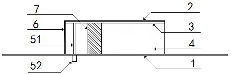
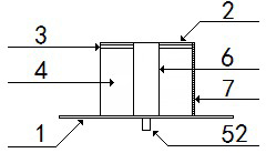
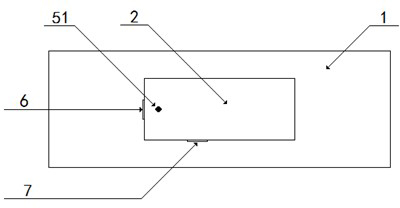
[0021] The planar inverted-F antenna has the characteristics of low profile, light weight, and low cost, so it is widely used in mobile terminal equipment. The planar inverted-F antenna is different from the general microstrip antenna. The radiation plate and the floor are connected by a short-circuit board, so the volume is reduced to one-half of the ordinary microstrip antenna, and the position and width of the short-circuit board are fixed. Through the research, it is found that the position and width of the short-circuit board of the planar inverted F antenna have an influence on the antenna's operating frequency, pattern, bandwidth and other parameters. Therefore, by changing the position and width of the short-circuit board, the purpose of adjusting the operating frequency, pattern and other parameters of the planar inverted-F antenna can be achieved.

[0022] The invention proposes a novel antenna for changing the working frequency of the planar inverted F antenna, whic...


PUM


Abstract

The invention discloses a variable-frequency microstrip antenna which comprises a floor, a radiant plate, a connector and at least two short circuit plates, wherein the connector is connected to the radiant plate through a feeding point arranged on the radiant plate; electromagnetic radiation is formed by excitation to the radiant plate through the connector from the downside of the floor; and the conduction state of the short circuit plates is controllable, one ends of the short circuit plates are connected to the radiant plate through connecting points arranged at the edge of the radiant plate and the other ends of the short circuit plates are connected to the floor, and the connecting state of the radiant plate and the floor can be controlled through controlling the conduction state of the short circuit plates. According to the variable-frequency microstrip antenna, the working frequency is changed through changing the conduction state of the short circuit plates; and the variable-frequency microstrip antenna works in a wider frequency band, and the antenna performance is improved.

Description

technical field [0001] The invention relates to a design method of a frequency-variable microstrip antenna, in particular to a frequency-variable microstrip antenna in which a radiation plate and a floor are connected through a plurality of short-circuit boards, and the on / off state of the short-circuit board is controllable. Background technique [0002] The rapid development of today's wireless communication technology has driven the development of multi-mode mobile terminals. Since the working frequency bands of various communication standards are different, the antenna of the mobile terminal needs to support multiple working frequency bands at the same time. However, the traditional microstrip antenna is difficult to meet the requirements of miniaturization, broadband, and multi-band at the same time due to the limitation of the basic relationship of size, bandwidth, and efficiency. At present, most multi-mode mobile terminals use multi-frequency antennas or multi-antenn...

Claims


Application Information

Patent Timeline
IPC IPC(8): H01Q1/36H01Q1/38H01Q1/48H01Q13/08
Inventor 李校林楼思研
Owner CHONGQING UNIV OF POSTS & TELECOMM
Why Eureka
Try Eureka