
Motor control device

A technology of a control device and a motor, which is applied in the directions of motor control, motor generator control, AC motor control, etc., can solve the problems of poor motor 101 or three-phase line, unable to detect short-circuit fault of converter 105, etc., and achieve reliable detection. Effect

Active Publication Date: 2011-11-23
HONDA MOTOR CO LTD
View PDF9 Cites 9 Cited by
  • Summary
  • Abstract
  • Description
  • Claims
  • Application Information

AI Technical Summary

Problems solved by technology

In this state, since both switch parts 5a and 5b of any corresponding arm are not simultaneously in the conduction state, the short circuit of the inverter 105 cannot be detected by the short circuit detection function of the invention described in Patent Document 1. Fault
If the inverter 105 is in a short-circuit failure state but no short-circuit failure is detected, the inverter ECU 111 does not perform the above-mentioned three-phase short-circuit control, so eventually a malfunction occurs in the motor 101 or the three-phase line.

Method used


Image

  • Motor control device
  • Motor control device
  • Motor control device

Examples


no. 1 approach

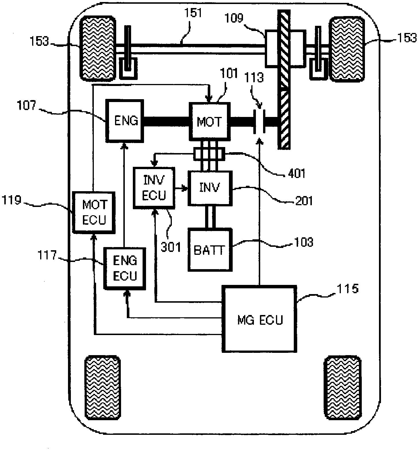
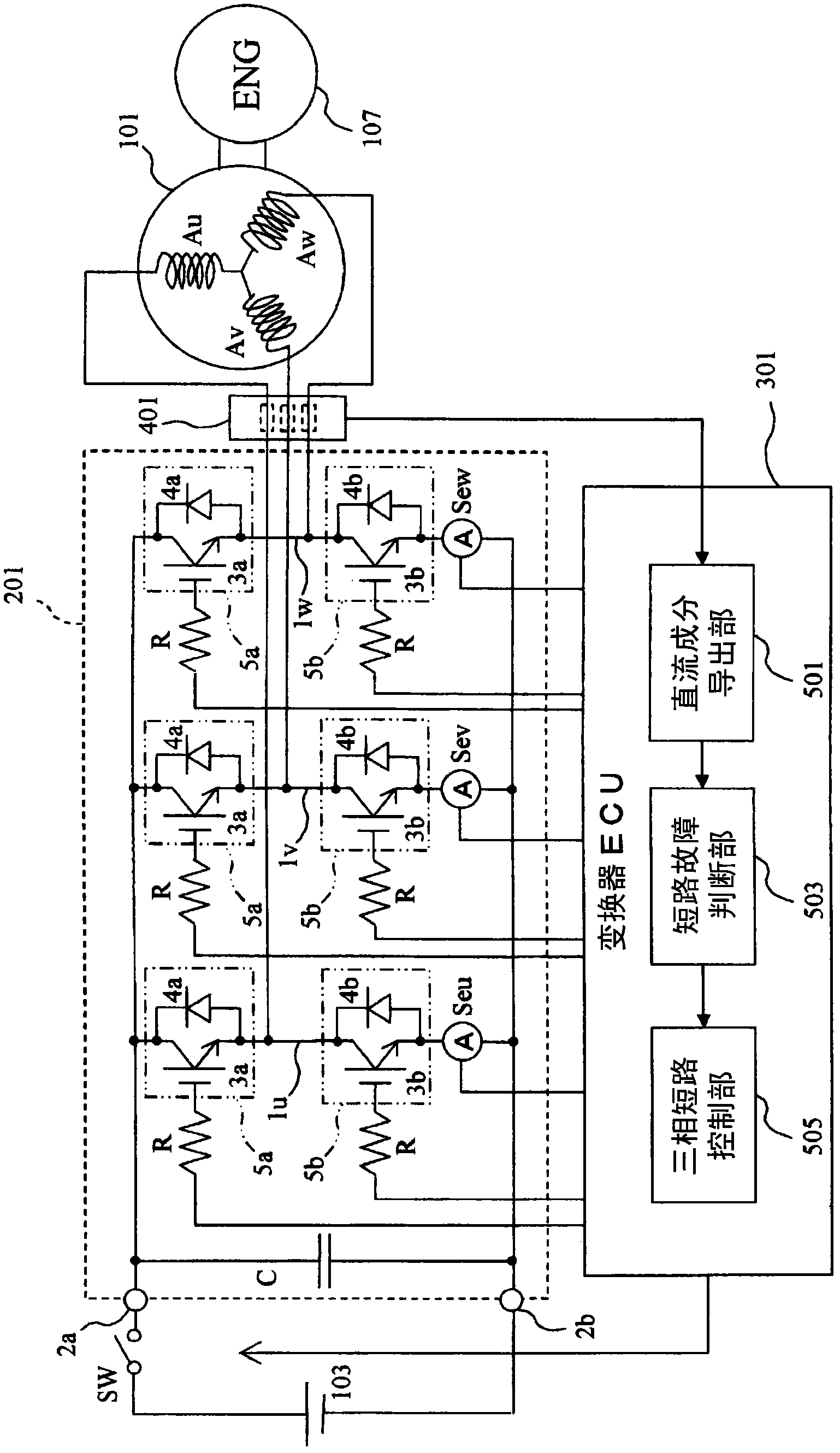
[0047] figure 1 It is a block diagram showing the internal structure of the HEV equipped with the electric motor control apparatus concerning this invention. figure 1 The shown HEV (hereinafter simply referred to as "vehicle") includes an electric motor (MOT) 101, a battery (BATT) 103, an inverter (INV) 201, an internal combustion engine (ENG) 107, a management ECU (MG ECU) 115, an engine ECU ( ENG ECU) 117 , motor ECU (MOT ECU) 119 , inverter ECU (INV ECU) 301 , phase current sensor 401 , clutch 113 , gearbox 109 , drive shaft 151 , and drive wheel 153 . It should be noted that the components other than the converter 201, the converter ECU 301, and the phase current sensor 401 are the same as those provided in the Figure 14 The corresponding structural elements on the vehicle are the same. Thus, in figure 1 in, right with Figure 14 Common structural elements are marked with the same reference symbol.

[0048] exist figure 1 In the vehicle shown, with Figure 14 Also...

no. 2 approach

[0068] Inverter ECUs 301 , 303 of the first embodiment may not correctly detect a short-circuit failure of inverters 201 , 203 when phase current sensor 401 fails. For example, the phase current value detected by the phase current sensor 401 such as Figure 12 fixed as shown in ratio Figure 4 In the event of a failure at a value such as a large threshold value Ith shown, converter ECU 301 , 303 erroneously judges that inverter 201 , 203 has a short-circuit failure.

[0069] Converter ECUs 301 and 303 of the first embodiment described above determine that a short-circuit fault has occurred in converters 201 and 203 when at least one of the absolute values ​​of DC component values ​​of the three phase currents exceeds threshold Ith. However, the inverter ECU 305 of the second embodiment judges that the inverters 201 and 203 are short-circuited based on whether the result of comparing the absolute values ​​of the DC component values ​​of the three phase currents with the thresh...


PUM


Abstract

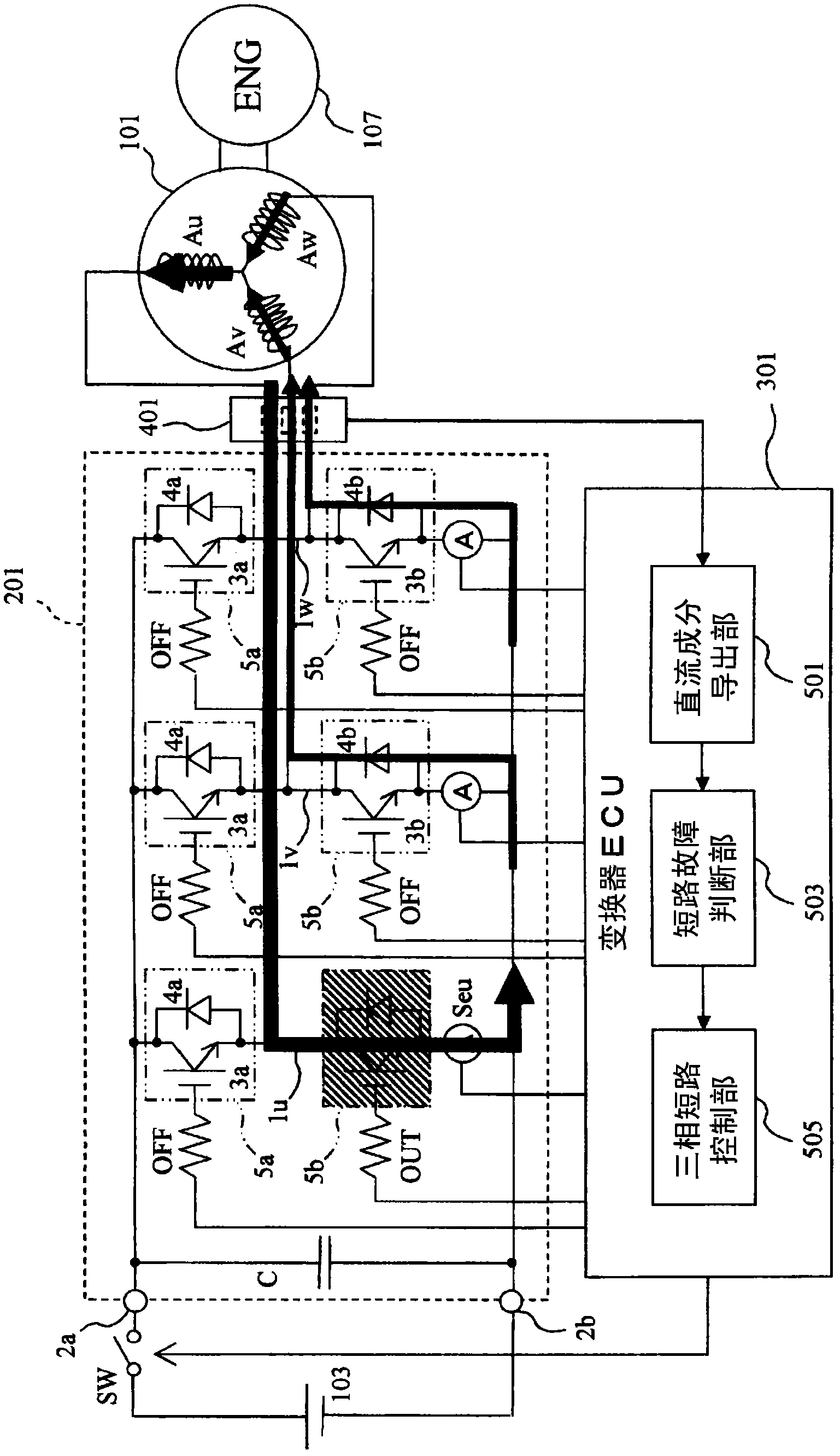
Provided is a motor control device including a switch unit having a switching element and a freewheeling diode connected in parallel to the switching element. Power is supplied from a direct current power source to the switch unit via an inverter having a plurality of phases and arranged at the positive electrode side and the negative electrode side of an arm of each of the phases. The motor control device includes: a phase current detection unit which detects current of each phase flowing between the inverter and the motor; a DC component derivation unit which derives a DC component of current of each phase; and a shortcircuit failure check unit which determines that a shortcircuit failure has occurred in the inverter if at least one of the DC components in the phase current derived by the DC component derivation unit exceeds a threshold value. Accordingly, even if the motor control is stopped, the shortcircuit failure of the inverter can be detected.

Description

technical field [0001] The present invention relates to a control device for a motor supplied with electric power from a DC power supply via a multi-phase converter in which a switch unit including a switching element and a return diode connected in parallel to the switching element is provided in each The positive side and the negative side of the arm of the phase. Background technique [0002] HEV (Hybrid Electrical Vehicle: hybrid electric vehicle) travels with the driving force of an internal combustion engine and / or an electric motor. Figure 14 is a block diagram showing the internal structure of HEV. exist Figure 14 In the illustrated HEV (hereinafter simply referred to as “vehicle”), driving force from an internal combustion engine (ENG) 107 and / or an electric motor (MOT) 101 is transmitted to drive wheels 153 via a gearbox 109 and a drive shaft 151 . In addition, in Figure 14 In the illustrated vehicle, the rotor of the electric motor 101 is directly connected to...

Claims


Application Information

Patent Timeline
Patent Type & Authority Applications(China)
IPC IPC(8): H02P27/06H02M7/48B60L3/00B60L11/14B60L50/16H02P21/22H02P27/08
CPCY02T10/642H02M2001/0009H02P29/021B60L3/003B60L11/14Y02T10/7077H02P27/06B60L50/16H02P29/0241H02M1/0009Y02T10/64Y02T10/7072Y02T10/70
Inventor 檀上靖之今井直树藤田裕二安乐文雄
Owner HONDA MOTOR CO LTD
Learn More