Split 360-degree automatic dried diet feeder for fishpond

A split-type, feeding machine technology, applied in fish farming, application, climate change adaptation, etc., can solve the problems of small activity range, complex structure, artificial feeding, etc., and achieve the effect of reducing workload and energy consumption.

Inactive Publication Date: 2013-01-09
吴为国
View PDF1 Cites 2 Cited by
  • Summary
  • Abstract
  • Description
  • Claims
  • Application Information

AI Technical Summary

Problems solved by technology

Usually the feeding machine is installed on the bank of the fishing pond, and the feed can only be thrown from one side. There is also a feeding machine with double-sided feeding, such as patent number: 200620165358.0, but this patent consists of two throwing motors, and the structure is complicated. It cannot feed in a large area, and the existing feeding machines are not suitable for feeding benthic aquatic products such as prawns, because the range of activities of prawns is small, and the prawns swim to a small range to eat and feed, which will cause damage due to excessive density , so most of the existing shrimp farming adopts manual feeding

Method used


Image

  • Split 360-degree automatic dried diet feeder for fishpond
  • Split 360-degree automatic dried diet feeder for fishpond
  • Split 360-degree automatic dried diet feeder for fishpond

Examples


Embodiment Construction

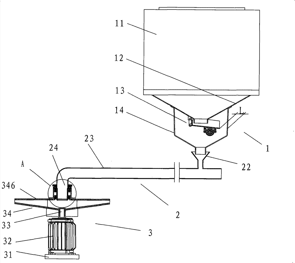
[0039] Below in conjunction with accompanying drawing, the present invention will be further described with specific embodiment, see Figure 1-20 :

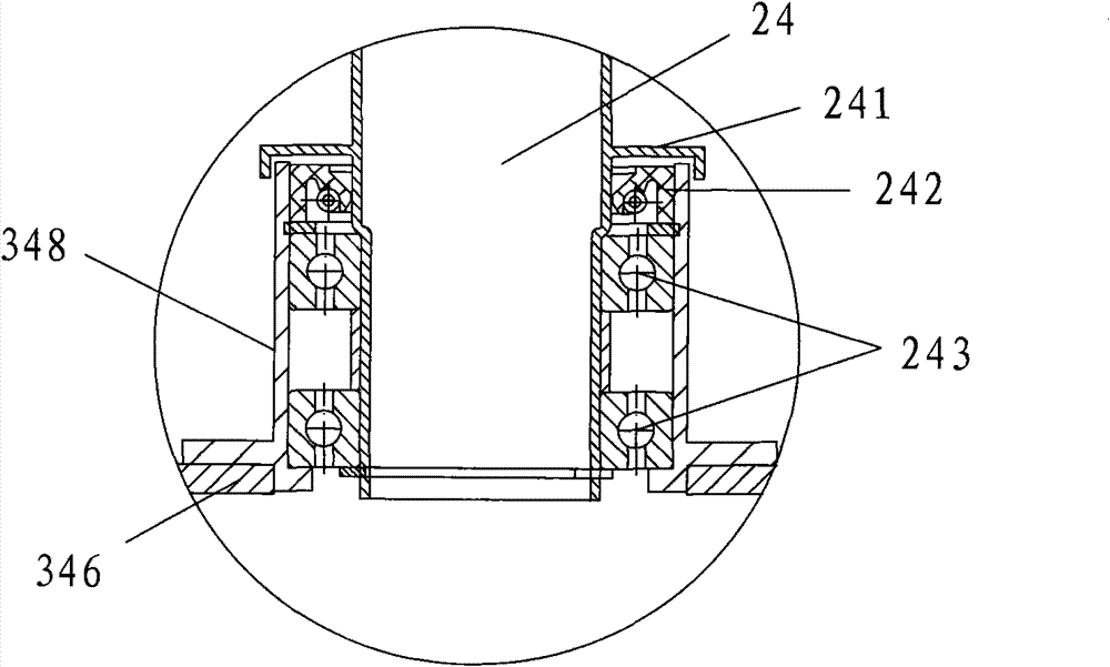
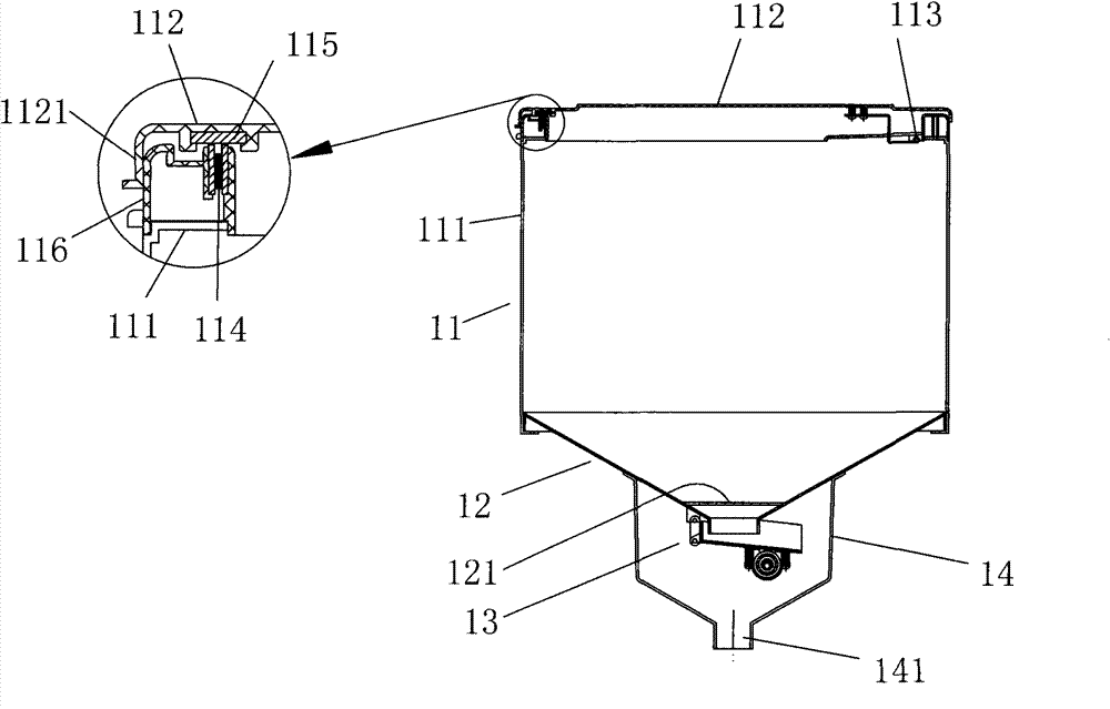
[0040] Split-type 360° automatic feeding machine for fishing ponds, a feeding mechanism 2 is provided between the feeding mechanism 1 and the throwing mechanism 3, and the feeding mechanism 1 is: a conical hopper 12 with a large upper part and a smaller one at the lower part The upper opening is upwardly connected with a material box 11, and the lower part is connected with a feeder 13; the throwing mechanism 3 is: the upper part of the 360° horizontal throwing tray 34 is centered with a feed inlet 3461, and the lower base 341 of the throwing tray 34 is There is a material throwing disc rotating shaft 33 downwards, and the material throwing disc rotating shaft 33 is driven by a power device or directly driven by a material throwing motor 32; the described feeding mechanism 2 is: one end of a horizontally arranged feeding pipe 23 ...


PUM


Abstract

A separate-type 360° automatic feeding device for ponds comprises a feeding mechanism (1), a throwing mechanism (3) and a conveying mechanism (2) provided between the feeding mechanism and the throwing mechanism. The feeding mechanism comprises a hopper (12) and a feeder (13). The upper part of the hopper is connected with a bait box (11), and the lower part thereof is connected with the feeder (13). The throwing mechanism comprises a bait throwing tray (34) and a rotor shaft (33) for the bait throwing tray. The upper part of the bait throwing tray is provided with a feeding port (3461) and the lower part thereof is provided with the rotor shaft (33) for the bait throwing tray. The rotor shaft is driven by a power device or a bait throwing motor (32). The conveying mechanism comprises a conveying pipe (23) transversely arranged. One end of the conveying pipe extends downwards to form a discharge port (24) and the other end thereof is provided with a feeding port (22). The feeding port of the conveying mechanism is connected with the discharge port of the feeding mechanism. A bearing is provided between the discharge port of the conveying mechanism and the feeding port of the throwing mechanism. The bait throwing tray rotates relative to the conveying mechanism. The feeding mechanism is provided on the bank and the throwing mechanism is provided in the pond. The bait throwing radius of the feeding device can be adjusted, therefore it is suitable for automatic feeding of varisized ponds.

Description

technical field [0001] The invention belongs to the technical field of aquaculture machinery, in particular to a split-type 360° automatic feeding machine for fish ponds. Background technique [0002] Feeding machine is an indispensable equipment for aquaculture. Usually the feeding machine is installed on the bank of the fishing pond, and the feed can only be thrown from one side. There is also a feeding machine with double-sided feeding, such as patent number: 200620165358.0, but this patent consists of two throwing motors, and the structure is complicated. It cannot feed in a large area, and the existing feeding machines are not suitable for feeding benthic aquatic products such as prawns, because the range of activities of prawns is small, and the prawns swim to a small range to eat and feed, which will cause damage due to excessive density , so most of the existing prawn farming adopts artificial feeding. Contents of the invention [0003] The purpose of the present...

Claims


Application Information

Patent Timeline
Patent Type & Authority Patents(China)
IPC IPC(8): A01K61/02
CPCA01K61/02A01K61/80Y02A40/81
Inventor 吴为国
Owner 吴为国
Why Eureka
Try Eureka