Motor with hollow ventilating main shaft and feeding machine with same

一种电动机、投饲机的技术,应用在电动组件、电气元件、机电装置等方向,能够解决不能大面积供料、过度密集伤害、活动范围少等问题,达到破碎率降低、覆盖面积大、防止饲料浪费的效果

Active Publication Date: 2014-12-31
吴海钧
View PDF4 Cites 0 Cited by
  • Summary
  • Abstract
  • Description
  • Claims
  • Application Information

AI Technical Summary

Problems solved by technology

Usually the feeding machine is installed on the bank of the fishing pond, and the feed can only be thrown from one side. There is also a feeding machine with double-sided feeding, such as patent number: 200620165358.0, but this patent consists of two throwing motors, and the structure is complicated. It cannot feed in a large area, and the existing feeding machines are not suitable for feeding benthic aquatic products such as prawns, because the range of activities of prawns is small, and the prawns swim to a small range to eat and feed, which will cause damage due to excessive density , so most of the existing shrimp farming adopts manual feeding

Method used


Image

  • Motor with hollow ventilating main shaft and feeding machine with same
  • Motor with hollow ventilating main shaft and feeding machine with same
  • Motor with hollow ventilating main shaft and feeding machine with same

Examples


Embodiment Construction

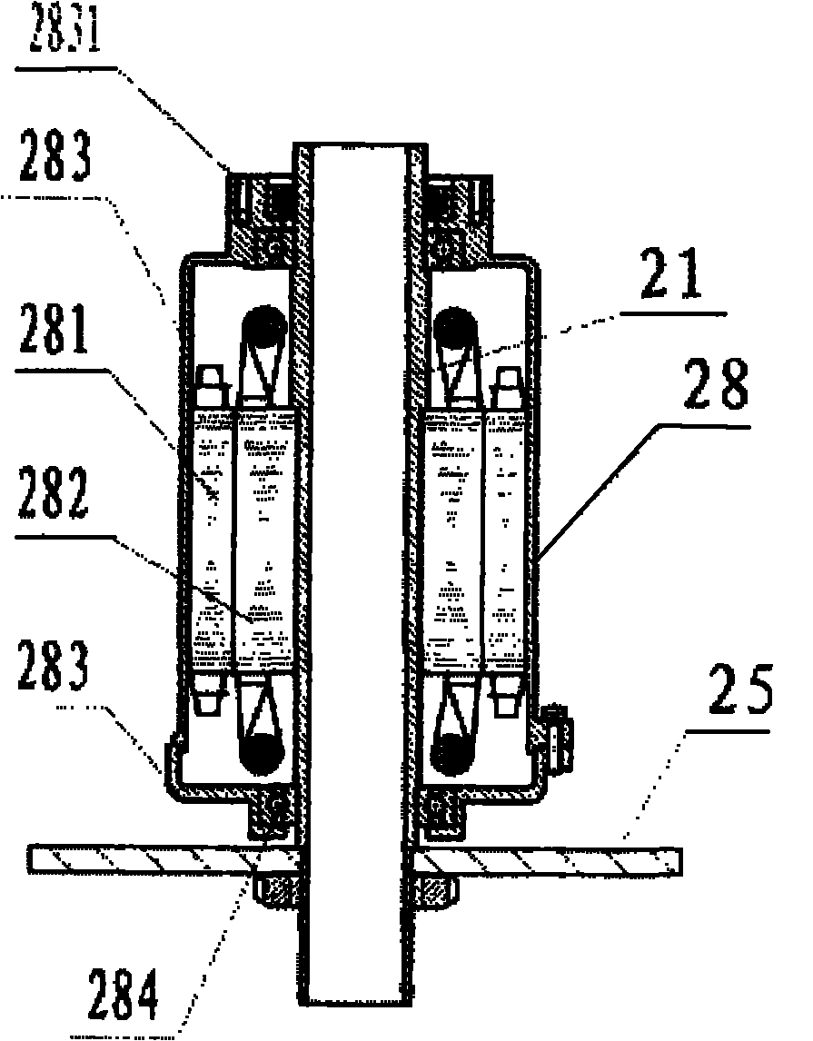
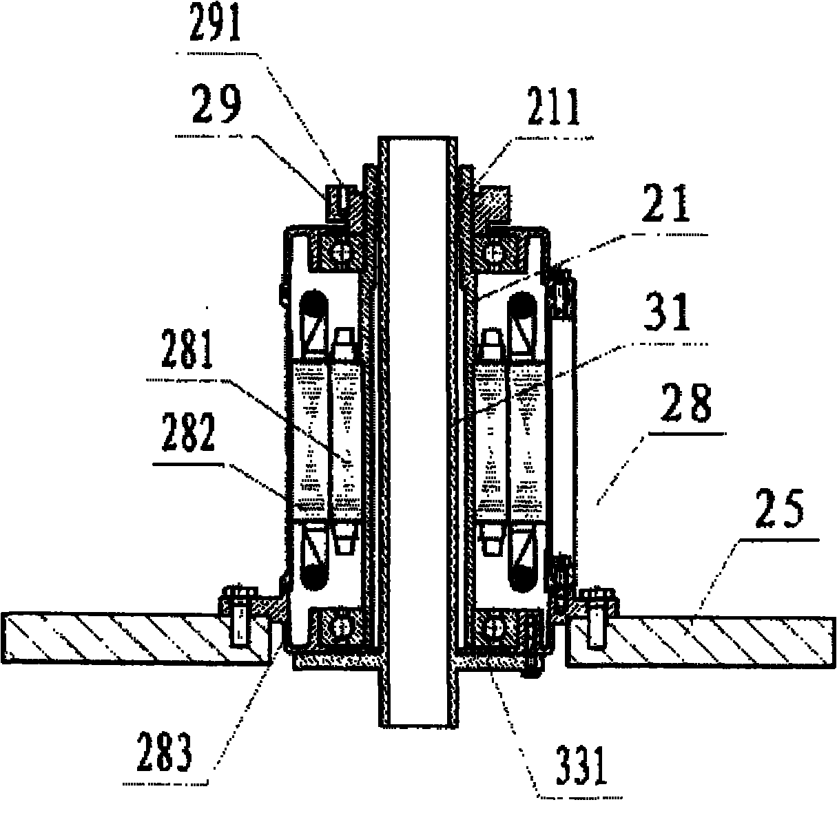
[0017] Below in conjunction with accompanying drawing, the present invention will be further described with specific embodiment, see Figure 1-25 : the motor with hollow ventilated main shaft of the present invention mainly is made up of stator 282, rotor 281, main shaft 21, bearing 284 etc., and electric motor comprises AC and DC motor, and described main shaft 21 is the structure of hollow, and the lower end of casing 283 is connected There is a flange, a bearing 284 is arranged between the housing 283 and the main shaft 21, the stator 282 is fixed on the housing 283, the housing 283 is connected to the base 25 through the flange, and the rotor 281 is fixed on the main shaft 21 to form an inner rotor motor ; or the stator 282 is fixed on the main shaft 21, the rotor 281 is fixed on the housing, and the main shaft 21 is fixed on the frame 25 to form an outer rotor motor.

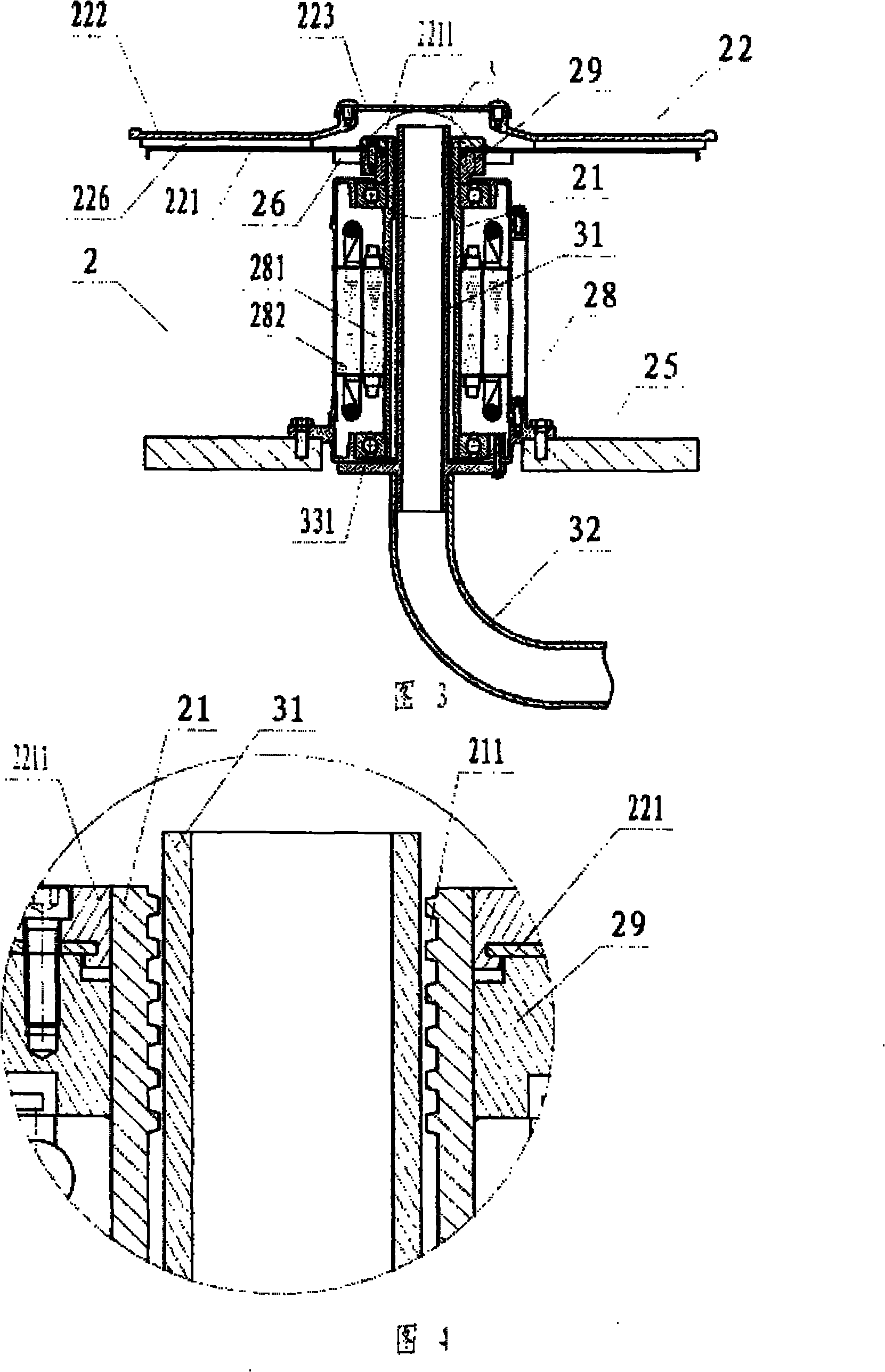
[0018]One end of the main shaft 21 of the above-mentioned inner rotor motor is fixed with a flange 29 th...


PUM


Abstract

The invention belongs to the technical field of aquaculture machines, and particularly relates to a 360-degree feed throwing disc and a fishpond feeding machine with the feed throwing disc. In the 360-degree feed throwing disc, a motor shaft mounting hole is formed on the middle part of a base; a disc cover of which the middle part is provided with a feed inlet is arranged on the base; feed throwing guiding plates are distributed radially outwards at the position with a certain radius between the base and the disc cover; outer end parts of the guiding plates are arranged at intervals with different lengths, so that thrown feed is far or close in distance; and a feed throwing channel is formed between the two adjacent guiding plates. A feed discharge nozzle of a feeding mechanism is opposite to or is inserted into the feed inlet of a feed throwing mechanism, wherein in the feeding mechanism, an opening on the upper part of a conical hopper which is large in the upper and small in the lower part is connected with a feed box upwards, the lower part of the conical hopper is connected with the feed discharge nozzle, and a feeder is arranged on an opening on the lower part of the hopper in the feed discharge nozzle; and in the feed throwing mechanism, the feed inlet is formed in the middle of the upper part of the 360-degree feed throwing disc. The feeding machine can be mounted integrally or in a split mode, and when mounted in a split mode, a feed conveying mechanism is arranged between the feed throwing mechanism and the feeding mechanism.

Description

technical field [0001] The invention belongs to the technical field of aquaculture machinery, in particular to an electric motor with a hollow ventilated main shaft and a feeding machine with the electric motor which feeds from the through hole of the main shaft of the electric motor. Background technique [0002] Feeding machine is an indispensable equipment for aquaculture. Usually the feeding machine is installed on the bank of the fishing pond, and the feed can only be thrown from one side. There is also a feeding machine with double-sided feeding, such as patent number: 200620165358.0, but this patent consists of two throwing motors, and the structure is complicated. It cannot feed in a large area, and the existing feeding machines are not suitable for feeding benthic aquatic products such as prawns, because the range of activities of prawns is small, and the prawns swim to a small range to eat and feed, which will cause damage due to excessive density , so most of the...

Claims


Application Information

Patent Timeline
Patent Type & Authority Patents(China)
IPC IPC(8): H02K7/00A01K61/00
CPCY02A40/70Y02A40/81
Inventor 吴为国吴海钧
Owner 吴海钧
Why Eureka
Try Eureka