360-degree feed throwing disc and fishpond feeding machine with feed throwing disc

A technology of throwing trays and feeding machines, which is applied in fish farming, applications, climate change adaptation, etc., can solve the problems of complex structure, small range of activities, manual feeding, etc., and achieve the effect of low energy consumption and reduced workload

Active Publication Date: 2014-04-16
ZHEJIANG FORDY MACHINERY
View PDF8 Cites 0 Cited by
  • Summary
  • Abstract
  • Description
  • Claims
  • Application Information

AI Technical Summary

Problems solved by technology

Usually the feeding machine is installed on the bank of the fishing pond, and the feed can only be thrown from one side. There is also a feeding machine with double-sided feeding, such as patent number: 200620165358.0, but this patent consists of two throwing motors, and the structure is complicated. It cannot feed in a large area, and the existing feeding machines are not suitable for feeding benthic aquatic products such as prawns, because the range of activities of prawns is small, and the prawns swim to a small range to eat and feed, which will cause damage due to excessive density , so most of the existing shrimp farming adopts manual feeding

Method used


Image

  • 360-degree feed throwing disc and fishpond feeding machine with feed throwing disc
  • 360-degree feed throwing disc and fishpond feeding machine with feed throwing disc
  • 360-degree feed throwing disc and fishpond feeding machine with feed throwing disc

Examples


Embodiment Construction

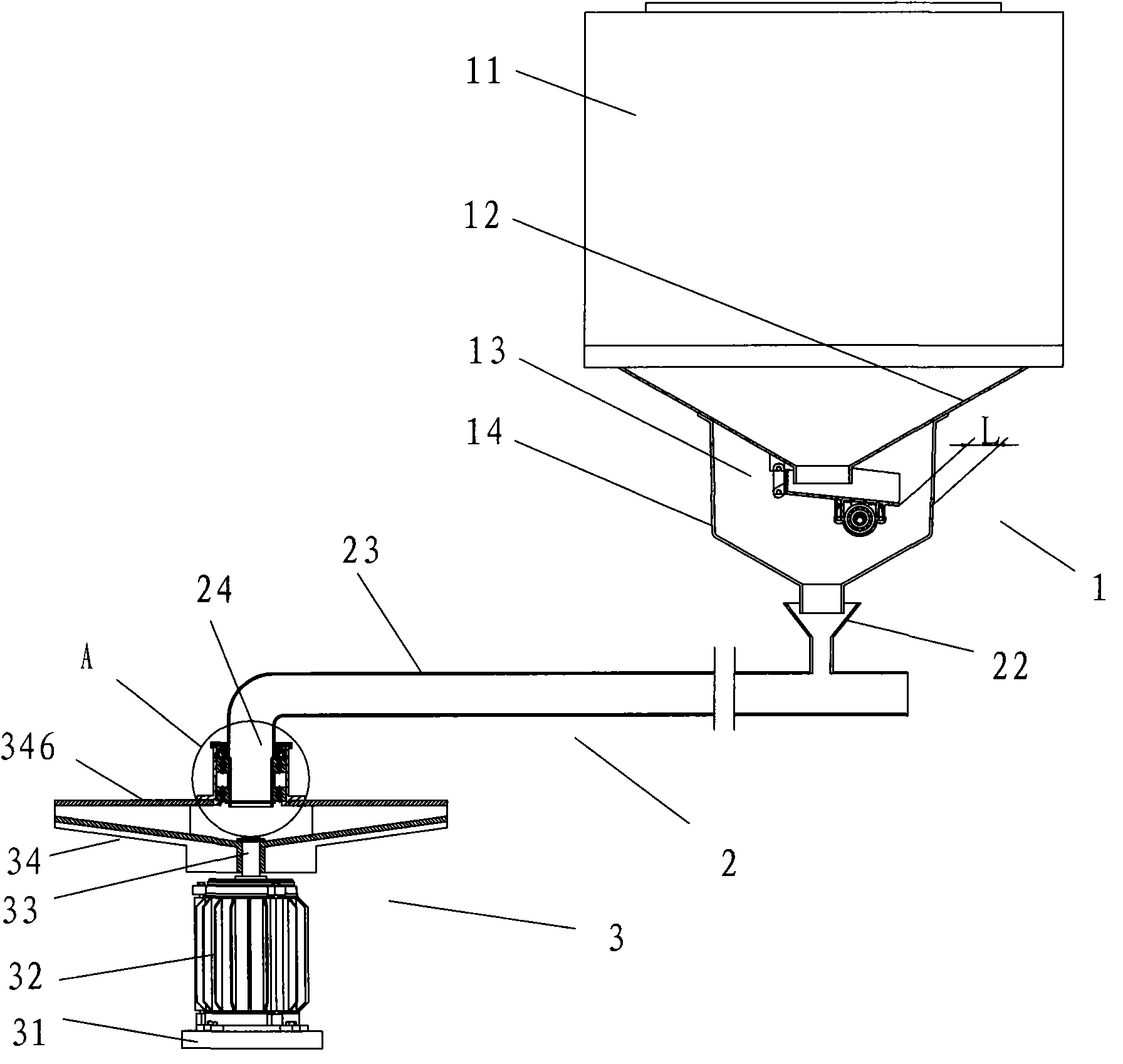
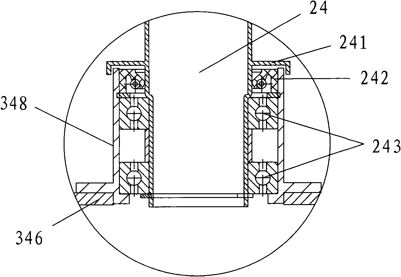
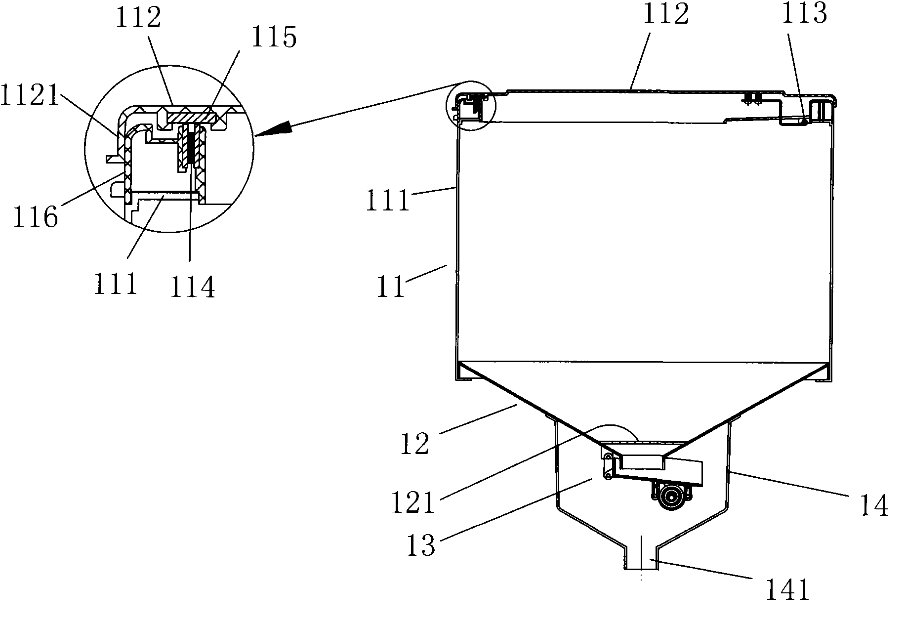
[0044] Below in conjunction with accompanying drawing, the present invention will be further described with specific embodiment, see Figure 1-25 :

[0045] 360 ° throwing tray 34 (see Figure 12-16) is: a motor shaft mounting hole 347 is provided in the middle of the base 341, a disc cover 346 with a feed port 3461 in the middle is provided on the base 341, and a certain radius between the base 341 and the disc cover 346 is radial outward Evenly distributed with throwing guide plate 342, the outer end of guide plate 342 is long and has short interval setting (referring to Figure 13 ), so that the thrown feed is far and near, and a throwing channel 345 is formed between two adjacent guide plates 342. The lower surface of the base 341 is radially provided with a reinforcing rib 343 that generates cooling airflow downwards. The base 341 can be plastic or Made of aluminum die-casting, the throwing guide plate 342 is formed by metal stamping, the upper part of the throwing guid...


PUM


Abstract

The invention belongs to the technical field of aquaculture machines, and particularly relates to a 360-degree feed throwing disc and a fishpond feeding machine with the feed throwing disc. In the 360-degree feed throwing disc, a motor shaft mounting hole is formed on the middle part of a base; a disc cover of which the middle part is provided with a feed inlet is arranged on the base; feed throwing guiding plates are distributed radially outwards at the position with a certain radius between the base and the disc cover; outer end parts of the guiding plates are arranged at intervals with different lengths, so that thrown feed is far or close in distance; and a feed throwing channel is formed between the two adjacent guiding plates. A feed discharge nozzle of a feeding mechanism is opposite to or is inserted into the feed inlet of a feed throwing mechanism, wherein in the feeding mechanism, an opening on the upper part of a conical hopper which is large in the upper and small in the lower part is connected with a feed box upwards, the lower part of the conical hopper is connected with the feed discharge nozzle, and a feeder is arranged on an opening on the lower part of the hopper in the feed discharge nozzle; and in the feed throwing mechanism, the feed inlet is formed in the middle of the upper part of the 360-degree feed throwing disc. The feeding machine can be mounted integrally or in a split mode, and when mounted in a split mode, a feed conveying mechanism is arranged between the feed throwing mechanism and the feeding mechanism.

Description

technical field [0001] The invention belongs to the technical field of aquaculture machinery, in particular to a 360-degree throwing tray and a fish pond feeding machine equipped with the throwing tray. Background technique [0002] Feeding machine is an indispensable equipment for aquaculture. Usually the feeding machine is installed on the bank of the fishing pond, and the feed can only be thrown from one side. There is also a feeding machine with double-sided feeding, such as patent number: 200620165358.0, but this patent consists of two throwing motors, and the structure is complicated. It cannot feed in a large area, and the existing feeding machines are not suitable for feeding benthic aquatic products such as prawns, because the range of activities of prawns is small, and the prawns swim to a small range to eat and feed, which will cause damage due to excessive density , so most of the existing prawn farming adopts artificial feeding. SUMMARY OF THE INVENTION [0...

Claims


Application Information

Patent Timeline
Patent Type & Authority Patents(China)
IPC IPC(8): A01K61/02
CPCY02A40/70Y02A40/81
Inventor 吴为国
Owner ZHEJIANG FORDY MACHINERY
Why Eureka
Try Eureka