A pneumatic metal can clamp

A technology of metal cans and clamps, applied in the direction of metal processing equipment, metal processing machinery parts, clamping, etc.

Active Publication Date: 2011-11-30
汕头市东方科技有限公司
View PDF5 Cites 2 Cited by
  • Summary
  • Abstract
  • Description
  • Claims
  • Application Information

AI Technical Summary

Problems solved by technology

[0004] In view of the deficiencies in the prior art, the purpose of the present invention is to provide a pneumatic metal tank clamp, which has the characteristics of firm clamping, uniform and adjustable cla

Method used


Image

  • A pneumatic metal can clamp
  • A pneumatic metal can clamp
  • A pneumatic metal can clamp

Examples


Embodiment Construction

[0014] The specific implementation manner of the present invention will be further described below in conjunction with the accompanying drawings.

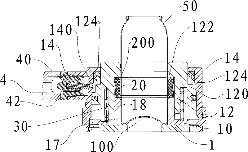
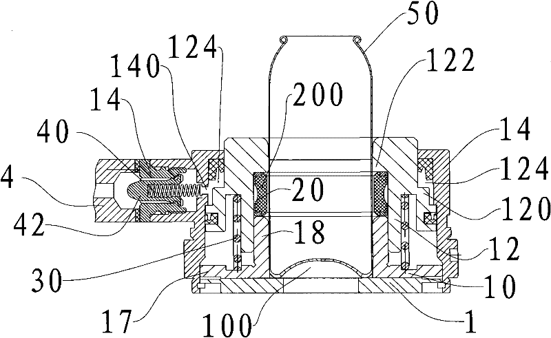
[0015] Please refer to figure 2 One embodiment shown is a pneumatic metal can clamp, including a high-pressure gas supply system. The metal can clamp includes a base 1 and an annular positioning plate 10 fixed on the base 1, which can The cylinder body 12 slidably sleeved on the outside of the annular positioning plate 10, and the housing 14 fixed to the base 1, the housing 14 is provided with an air inlet 140 connected to the air supply system; the center of the annular positioning plate 10 For the channel 100 for accommodating and clamping the metal can, the top of the cylinder body 12 is provided with an annular protrusion 122 inwardly, and an annular boss 120 is arranged outside the cylinder body 12, the annular boss 120, the shell 14 and the The cylinder block 12 forms a closed air chamber 124; there is an end distance betwe...


PUM


Abstract

The invention discloses a pneumatic metal can clamping unit which comprises a high pressure air supply system, a base, an annular positioning plate arranged on the base, a cylinder capable of being sleeved outside of the annular positioning plate, a shell fixedly connected with the base and an air inlet which is arranged on the shell and connected with the air supply system, wherein the center of the annular positioning plate is provided with a channel for accommodating and clamping a metal can; the top of the cylinder is inwards provided with an annular bump; an annular boss is arranged outside the cylinder; the annular boss, the shell and the cylinder form a closed air chamber; a certain distance is reserved between the lower end of the cylinder and the annular positioning plate; and the lower end of the bump and the annular positioning plate form an annular groove in-built with an elastic rubber block. By adopting the pneumatic metal can clamping unit in the technical scheme, the clamping is reliable, the clamping force is uniform and adjustable, the operation is simple, the centering property is excellent, a centering error generated by relaxation can be avoided, and appearance defects such as pollution, scratches and the like on an aluminium pot product can be avoided.

Description

technical field [0001] The invention relates to a neck tightening machine for metal cans, in particular to a clamper for clamping metal cans during the neck tightening operation. Background technique [0002] After the metal aerosol can is printed on the outer surface, it needs to narrow the mouth of the can through a neck machine and perform flanging and other processes. Each process requires a clamp to firmly clamp the product and send it to the next station. Because The tank wall is thin, which can easily lead to deformation of the product clamp or unstable clamping, resulting in falling out and scrapping. [0003] Please refer to figure 1 The shown existing aluminum aerosol can clamp is clamped by a combination of multi-piece nylon clamping sleeve 101 and spring 501 , and the nylon clamping sleeve 101 is located in the housing 401 of the clamp. Before the aluminum can enters the clamp, it is necessary to press down the pressure wheel 301 installed on the lever 201 with...

Claims


Application Information

Patent Timeline
IPC IPC(8): B25B11/00B23Q3/06
Inventor 李君杨海林
Owner 汕头市东方科技有限公司
Why Eureka
Try Eureka