A method for placing a vacuum glass support

A technology for vacuum glass and supports, applied in the field of laying vacuum glass supports, can solve the problems of reduced production efficiency, low support efficiency, single function, etc., and achieves the solution of unsmooth airflow, scientific and reasonable design, and simple overall structure. Effect

Active Publication Date: 2011-11-30
左树森
View PDF3 Cites 3 Cited by
  • Summary
  • Abstract
  • Description
  • Claims
  • Application Information

AI Technical Summary

Problems solved by technology

At present, the method of laying vacuum glass supports is generally a square array dot arrangement or a wire arrangement, and can also be mixed. The disadvantage is that the positioning position of the support is unstable, and the efficiency of the support is low. And it can only play a supporting role with a single function; more importantly, using wire or rod as a support will increase the suction resistance, making the negative pressure value and stress in the vacuum glass gap uneven, which not only prolongs the The time of vacuuming reduces the production efficiency and also seriously affects the quality of vacuum glass

Method used


Image

  • A method for placing a vacuum glass support
  • A method for placing a vacuum glass support
  • A method for placing a vacuum glass support

Examples


Embodiment 1

[0021] Embodiment 1: a kind of laying method of vacuum glass support, the steps are:

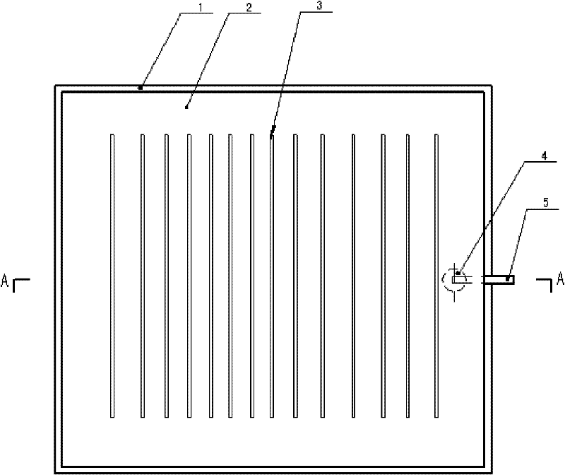
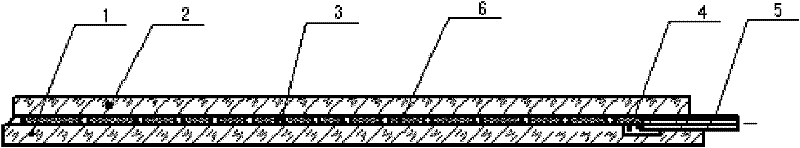
[0022] (1) Cut the upper glass 2 and the substrate glass 1 into substantially the same size. Generally, the upper glass is slightly smaller than the substrate glass, and then a suction groove 4 is made on one side of the substrate glass, and then sprayed, Apply a layer of adhesive 6 on the substrate glass by shower coating or brush coating to form an adhesive film layer. The adhesive is made of glass heat insulating material, and the glass heat insulating coating is an organic coating, such as polymer or resin, etc. , including inorganic coatings such as metal oxides and inorganic salts. For example, the glass heat insulation coating is made of urethane or resin high-temperature resistant organic glass coatings that can withstand high temperatures above 200 ° C, such as the alkyd produced by Shenzhen Dehou Technology Co., Ltd. Resin glass thermal insulation coating, the color of the coating ...

Embodiment 2

[0027] The difference from Example 1 is that the support wires or support rods arranged in parallel and uniform intervals are prefabricated in the support film layer in the glass heat insulation material, and the support film layer is directly placed between the upper glass and the substrate glass. Can.

[0028] Others are the same as in Example 1.

Embodiment 3

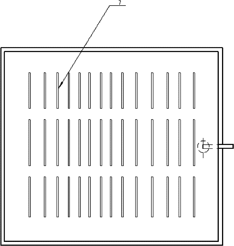
[0030] The difference from Embodiments 1 and 2 is that the support rods and support wires 7 are made intermittently, thereby improving the pumping efficiency.

[0031] Others are the same as in Example 1.


PUM


Abstract

The invention relates to a paving method of supports for vacuum glass, and the paving method comprises the steps: (1) tailoring upper glass and substrate glass and forming extraction grooves or holes on the side of the substrate glass or the plane of the upper glass; (2) parallelly and uniformly paving support wires or support rods on the glass substrate by bonding with an adhesive, wherein the distance between the support wires or support rods in the length direction and the edge of the substrate glass is 1-15 cm and the interval between the support wires or support rods is 2-20cm; and (3) placing extraction pipes in the extraction grooves, filling sealing materials at the periphery of the upper glass and substrate glass, introducing the upper glass and glass substrate into a furnace, heating to 100-500 DEG C and vacuumizing to obtain a finished product. Through the paving method provided by the invention, the support wires or support rods are directly bonded onto the substrate glass or directly processed into film layers containing the support wires or support rods, thereby realizing the rapid paving of the supports for the vacuum glass; the paving method is accurate in positioning and high in paving efficiency; and the film layers further enhance the heat-insulation performance of the vacuum glass, thus effectively improving the production efficiency and performance of the vacuum glass.

Description

technical field [0001] The invention belongs to the field of vacuum glass, in particular to a laying method of a vacuum glass support. Background technique [0002] The layout of the vacuum glass support has an important impact on the quality of the vacuum glass. At present, the method of laying vacuum glass supports is generally a square array dot arrangement or a wire arrangement, and can also be mixed. The disadvantage is that the positioning position of the support is unstable, and the efficiency of the support is low. And it can only play a supporting role with a single function; more importantly, using wire or rod as a support will increase the suction resistance, making the negative pressure value and stress in the vacuum glass gap uneven, which not only prolongs the The time of vacuuming reduces production efficiency and also seriously affects the quality of vacuum glass. Contents of the invention [0003] The purpose of the present invention is to overcome the d...

Claims


Application Information

Patent Timeline
Patent Type & Authority Applications(China)
IPC IPC(8): C03C27/10C03C27/12
Inventor 左树森
Owner 左树森
Why Eureka
Try Eureka