movable rail switch

A technology for moving rails and rails, applied in the directions of tracks, roads, railway signals, etc., can solve the problems of hindering the passage of the transmission part of the equipment, and achieve the effects of simple structure, solid foundation and low cost.

Inactive Publication Date: 2011-11-30
YANGZHOU KAISITE MACHINERY
View PDF0 Cites 20 Cited by
  • Summary
  • Abstract
  • Description
  • Claims
  • Application Information

AI Technical Summary

Problems solved by technology

Due to the development of auxiliary transportation in modern mines, such as rack cars, rack trucks, pin-tooth carts and other equipment, the traditional movable railway switch cannot meet the requirements of these equipment. The main reason is that these equipment The transmission part is located in the middle of the rail, and the connection part of the traditional movable railway switch hinders the passage of the transmission part of these equipment

Method used


Image

  • movable rail switch
  • movable rail switch

Examples


Embodiment Construction

[0018] The following describes the technical solution of the present invention in detail through a best embodiment in conjunction with the accompanying drawings, but the protection scope of the present invention is not limited to the embodiment.

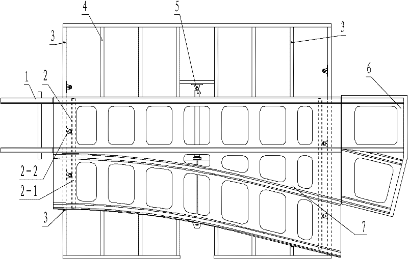
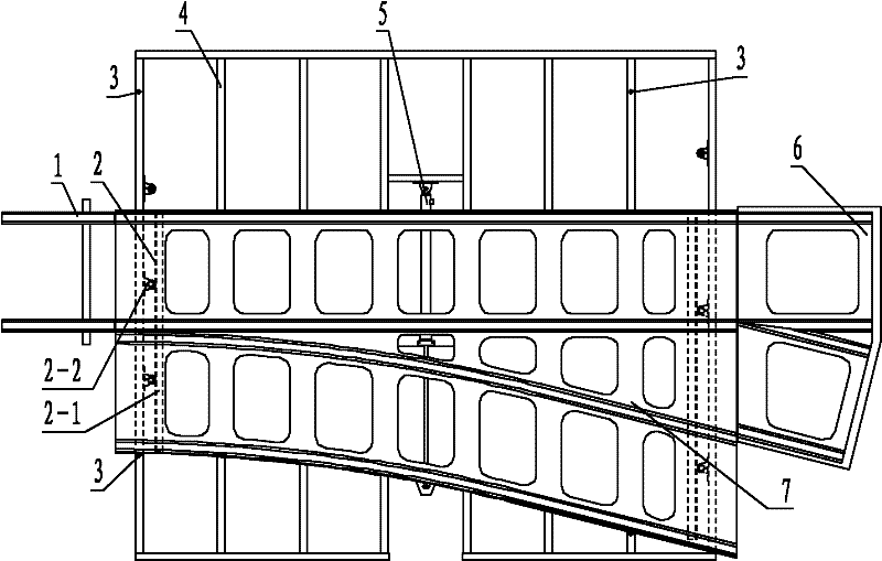
[0019] As shown in the figure, a kind of movable railway switch comprises a basic rail 1, a frog rail 6, a movable rail 7 and a sliding device, and the movable rail 7 is arranged between the basic rail 1 and the frog rail 6; the frog rail 6 includes Two groups of rails leading to different directions, the movable rails 7 are arranged side by side with two groups of rails corresponding to the frog rail 6, and the sliding device is arranged under the movable guide rail 7; the sliding device includes The guiding device 2, the basic frame 4, the driving device 5 and the limit 3 arranged on the sliding basic frame, the described guiding device 2 includes a guide rail 2-1 fixedly connected with the movable rail 7 and a guide wheel 2-2, the ...


PUM


Abstract

The invention discloses a movable railway switch. This movable railway switch comprises a basic rail (1) and a switch rail (6), and the switch rail (6) comprises more than two groups of rails leading to different directions, and in the basic rail (1) and switch rail ( 6) Movable rails (7) are arranged between them, and the movable rails (7) are arranged side by side with more than two groups of rails corresponding to the frog rails (6), and are arranged below the movable guide rails (7) There are sliding devices. The movable railway switch of this technical scheme can ensure the passage of transport vehicles with transmission components in the middle of the railway track, has convenient operation, simple structure, and meets the requirements of actual use after trial use.

Description

technical field [0001] The invention relates to the field of railway transportation, in particular to a movable railway switch. Background technique [0002] The railway track switch is an important part of the railway line. Locomotives, mine cars, etc. run on railway lines, and often need to enter another line from one line, which is realized by movable railway switch. The traditional movable railway switch is generally composed of a switch, a turnout rail and the connecting part between them. The point device includes the point rail and the basic rail. When the rolling stock, mine car, etc. pass the turnout and need to change direction, the point device acts to change the joint between the point rail and the basic rail in the point device, and the rolling stock, mine car, etc. Run in the set direction. Due to the development of auxiliary transportation in modern mines, such as rack cars, rack trucks, pin-tooth carts and other equipment, the traditional movable railway s...

Claims


Application Information

Patent Timeline
Patent Type & Authority Applications(China)
IPC IPC(8): E01B7/14B61L5/04
Inventor 邹舰汪邦正翁刘基曹磊
Owner YANGZHOU KAISITE MACHINERY
Why Eureka
Try Eureka