Automatic adjustment device for shoe clearance
A technology of automatic adjustment device and clearance, applied in the direction of slack adjuster, brake type, drum brake, etc., can solve the problems of difficult to assemble support components, foot brakes without brake levers, poor efficiency, etc., and achieve easy automatic assembly. Effect
- Summary
- Abstract
- Description
- Claims
- Application Information
AI Technical Summary
Problems solved by technology
Method used
Image
Examples
Embodiment 1
[0033] Refer to the attached Figure 1 ~ Figure 4 , Embodiment 1 of the present invention will be described.
[0034] (1) The overall structure of the drum brake device
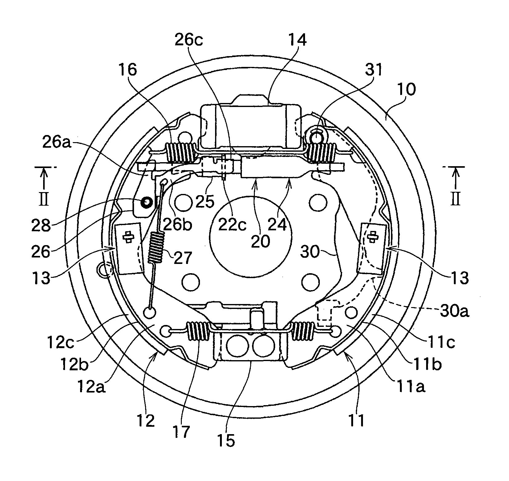
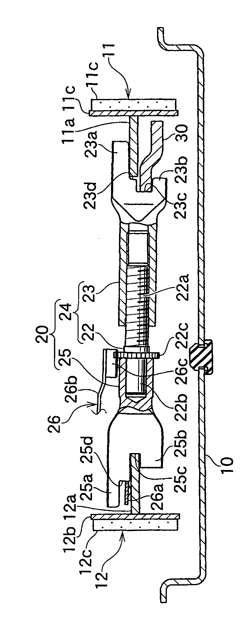
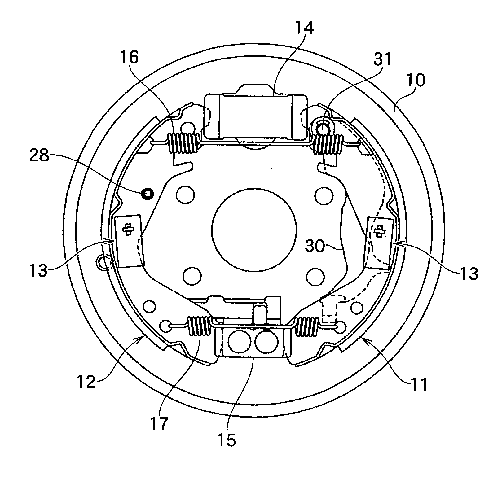
[0035] figure 1 A top view of a leading trailing (LT-shaped) drum brake device with a parking brake mechanism and an incremental shoe clearance automatic adjustment device, figure 2 represents its transverse cross-sectional view, image 3 It shows the top view of the drum brake device before assembly of the support assembly constituting the automatic shoe clearance adjustment device, Figure 4 It is a transverse cross-sectional view showing the drum brake device before the assembly of the support unit is completed.
[0036] exist figure 1 In the drum brake device of the present invention, reference numeral 10 represents the back plate fixed on the non-moving part of the vehicle by bolts etc., and a pair of brake shoes 11,12 are slidable by known shoe holders 13,13. way is supported.
[0037] The cross...
Embodiment 2
[0088] (1) Automatic adjustment device for shoe clearance
[0089] Figure 5 ~ Figure 7Another embodiment is shown. In this embodiment, the front end of the upper jaw 23a at one end of the support assembly 20 is extended to integrally form a hook-shaped middle jaw 23e, and the middle jaw 23e is embedded and engaged with a brake shoe. The rectangular engaging hole 11d in the shoe reinforcement rib 11a of the sheet 11.
[0090] Figure 5 It shows the top view of the leading trailing (LT-shaped) drum brake device with a parking brake mechanism and an incremental automatic adjustment device for shoe clearance, Figure 6 It is a cross-sectional view showing the drum brake device before the assembly of the support unit 20 is completed.
[0091] On the right flat portion of the nut member 23, a first stepped portion 23d is formed inside the upper jaw 23a, and a second stepped portion 23f is formed at the proximal end of the upper jaw 23a.
[0092] The middle jaw 23e is bent at ri...
Embodiment 3
[0121] In Embodiment 1 and Embodiment 2, the form in which the brake lever 30 is overlapped and arranged on the shoe reinforcement rib 11a of one brake shoe 11 is given, but the brake lever 30 can also be overlapped and arranged on the The form on the shoe reinforcing rib 12a of another brake shoe 12.
PUM
 Abstract
Description
Claims
Application Information
 - R&D
- Intellectual Property
- Life Sciences
- Materials
- Tech Scout
- Unparalleled Data Quality
- Higher Quality Content
- 60% Fewer Hallucinations
Browse by: Latest US Patents, China's latest patents, Technical Efficacy Thesaurus, Application Domain, Technology Topic, Popular Technical Reports.
© 2025 PatSnap. All rights reserved.Legal|Privacy policy|Modern Slavery Act Transparency Statement|Sitemap|About US| Contact US: help@patsnap.com


