Backlight module, surface light source module and light guide grid structure

A technology of backlight module and grid structure, which is applied in the field of surface light source modules that can emit light uniformly, and can solve the problems of long light guide distance consumption, difficult diffusion and homogenization of light-emitting diode point light sources, and inability to easily achieve flexibility, etc.

Active Publication Date: 2011-11-30
IND TECH RES INST
View PDF6 Cites 5 Cited by
  • Summary
  • Abstract
  • Description
  • Claims
  • Application Information

AI Technical Summary

Problems solved by technology

[0002] Most of the LED lighting modules used in light boxes, indicator lighting, and display purposes are direct-type or side-projection designs that use multiple arrays. The side-projection design is characterized by the use of a small number of LEDs. Through The light guide film emits light from the side-projection LED light source and the vertical surface light source, but the light utilization rate of the lamp is too low because the light guide distance is too long to consume light; the direct surface design can be applied to large-size and high-brightness lamps or backlights module, but the diffusion and homogenization of light-emitting diode point light sources is quite difficult. It requires a high-density multi-number light-emitting diode array (increased cost), or a certain distance of the optical path (that is, the thickness of the overall module becomes thicker), and a uniform diffusion Sheet or optical film, etc., can achieve the effect of surface light source and reduce the projection color pattern, but because the thickness of the whole module becomes thicker, it is not easy to realize the flexible effect

Method used


Image

  • Backlight module, surface light source module and light guide grid structure
  • Backlight module, surface light source module and light guide grid structure
  • Backlight module, surface light source module and light guide grid structure

Examples


Embodiment Construction

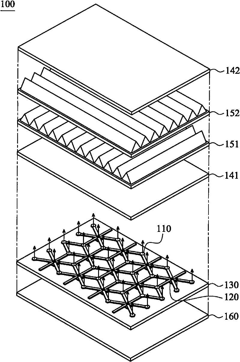
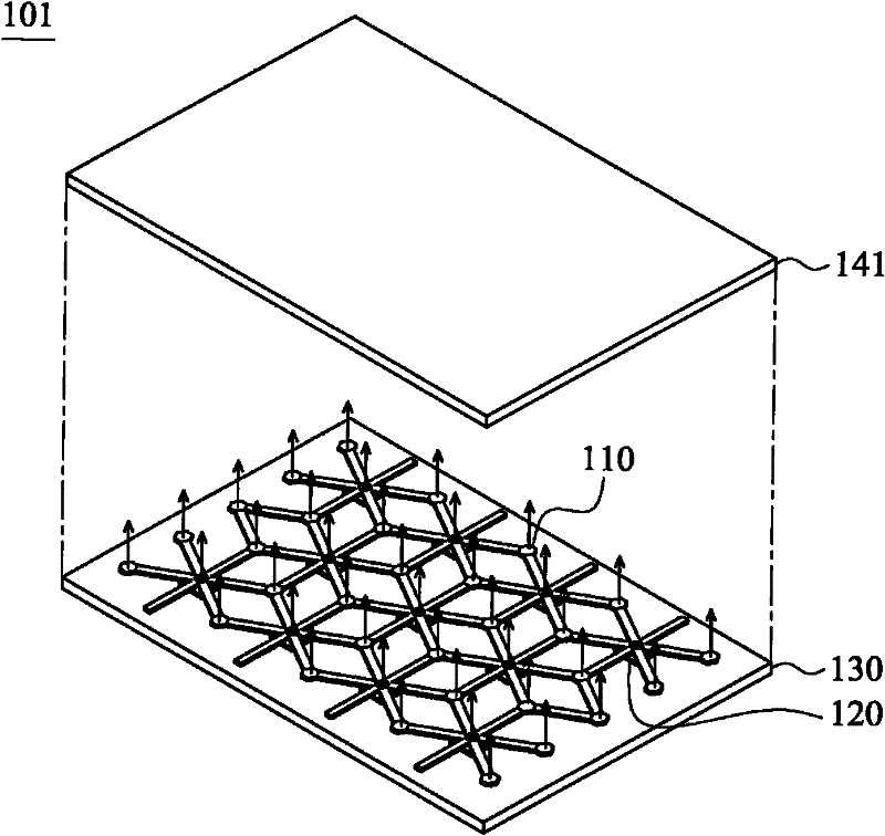
[0068] refer to Figure 1A , which is a backlight module 100 showing an embodiment of the present invention, including a light guide grid structure 110, a light source (light emitting diode) 120, a substrate 130, a diffusion film 141, a diffusion film 142, a prism sheet 151, a prism sheet 152, and a heat dissipation backplane 160. The light source 120 is disposed on the substrate 130 . Wherein, the prism sheet 151 may be a vertical row prism sheet, and the prism sheet 152 may be a horizontal row prism sheet. refer to Figure 1B , which is a characteristic part of the surface light source module (surface light source module 101 ) showing an embodiment of the present invention, including a light guide grid structure 110 , a light source (light emitting diode) 120 , a substrate 130 and a diffusion film 141 .

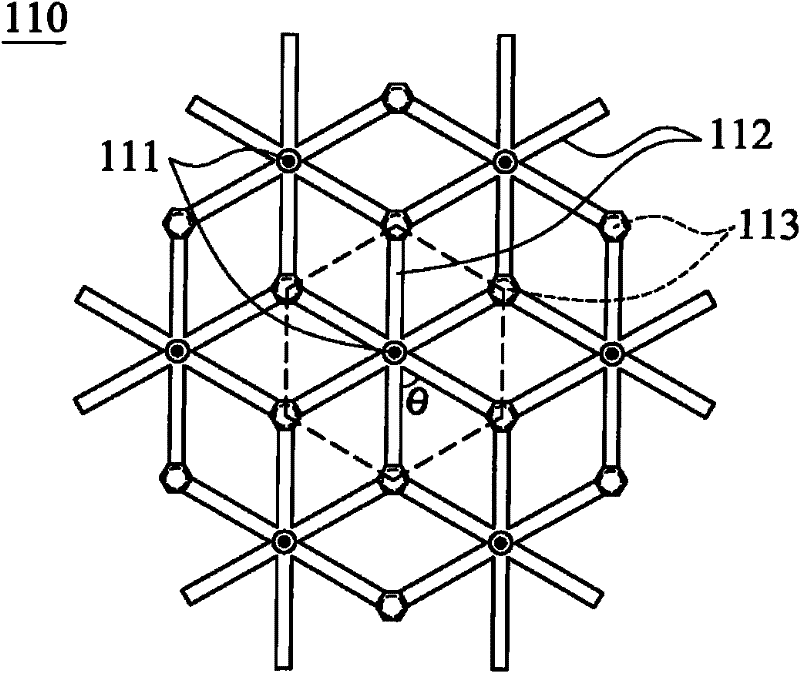
[0069] Figure 2A It is an embodiment showing the grid distribution of the light guide grid structure, Figure 2B It is a cross-sectional view showing the detailed stru...


PUM


Abstract

The invention provides a backlight module, an area light source module and a light guide grid structure. The area light source module comprises the light guide grid structure and multiple light sources, wherein the light guide grid structure is provided with multiple light distribution parts, multiple light guide pipes and multiple virtual light source light emergent parts; each light guide pipe is communicated with the light distribution parts and the virtual light source light emergent parts. Each light source is provided with a light ray and corresponds to the light distribution part, wherein the light ray contacts with the light distribution part, part of the light ray penetrates through the light distribution part and is emergent, and part of the light ray is reflected by the light distribution part, passes through the multiple light guide pipes and is emergent through the multiple virtual light source light emergent parts.

Description

technical field [0001] The present invention relates to a surface light source module, in particular to a surface light source module capable of emitting light uniformly. Background technique [0002] Most of the LED lighting modules used in light boxes, indicator lighting, and display purposes are direct-type or side-projection designs that use multiple arrays. The side-projection design is characterized by the use of a small number of LEDs. Through The light guide film emits light from the side-projection LED light source and the vertical surface light source, but the light utilization rate of the lamp is too low because the light guide distance is too long to consume light; the direct surface design can be applied to large-size and high-brightness lamps or backlights module, but the diffusion and homogenization of light-emitting diode point light sources is quite difficult. It requires a high-density multi-number light-emitting diode array (increased cost), or a certain d...

Claims


Application Information

Patent Timeline
Patent Type & Authority Applications(China)
IPC IPC(8): F21S8/00F21V8/00F21V17/00F21V19/00
Inventor 黄承扬戴晟杰许诏开
Owner IND TECH RES INST
Why Eureka
Try Eureka