Touch Screens, Touch Systems and Displays

A touch screen and touch object technology, applied in the fields of touch screen, touch system and display, can solve the problems of low resolution of infrared touch screen, complicated installation and debugging, high production cost of touch screen, etc.

Inactive Publication Date: 2011-11-30
BEIJING UNITOP NEW TECH CO LTD
View PDF5 Cites 4 Cited by
  • Summary
  • Abstract
  • Description
  • Claims
  • Application Information

AI Technical Summary

Problems solved by technology

[0004] However, the infrared touch screen has the following defects: due to the use of a large number of infrared components, and the installation and debugging are more complicated, the production cost of the touch screen is relatively high; Infrared touch screen has low resolution

Method used


Image

  • Touch Screens, Touch Systems and Displays
  • Touch Screens, Touch Systems and Displays
  • Touch Screens, Touch Systems and Displays

Examples


no. 1 example

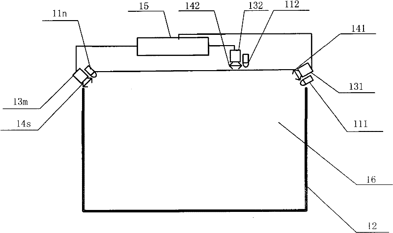
[0070] Such as figure 1 As shown, it is a schematic structural diagram of the first embodiment of the touch screen of the present invention, which may include at least two light sources 111, 112...11n, light absorbing strips 12, at least two direction sensors 131, 132...13m, and at least two light concentrating devices 141, 142...14s, the processing circuit 15, wherein m, n and s are natural numbers greater than or equal to 2.

[0071] At least two light sources 111, 112...11n are installed around the touch detection area 16 of the touch screen. The light absorbing strip 12 is installed around the touch detection area 16 . At least two direction sensors 131, 132...13m are respectively installed adjacent to at least two light sources 111, 112...11n, and there is at least one light source near each direction sensor. Specifically, the light source can be installed beside or above the direction sensor or below. At least two light concentrating devices 141, 142...14s are mounted...

no. 3 example

[0089] Such as Figure 5 As shown, it is a schematic structural diagram of the third embodiment of the touch screen of the present invention, which may include at least two light sources 111, 112...11n, at least two direction sensors 131, 132...13m, retro-reflective strips 18, and at least two concentrators Devices 141, 142...14s, processing circuit 15, wherein m, n and s are natural numbers greater than or equal to 2.

[0090] At least two light sources 111, 112...11n are installed around the touch detection area 16 of the touch screen. At least two direction sensors 131, 132...13m are installed adjacent to at least two light sources 111, 112...11n respectively, with at least one light source near each direction sensor. A retro-reflective strip 18 is installed around the touch detection area 16 . At least two light concentrating devices 141, 142...14s are respectively installed in front of at least two direction sensors 131, 132...13m, and each direction sensor has at least...

no. 4 example

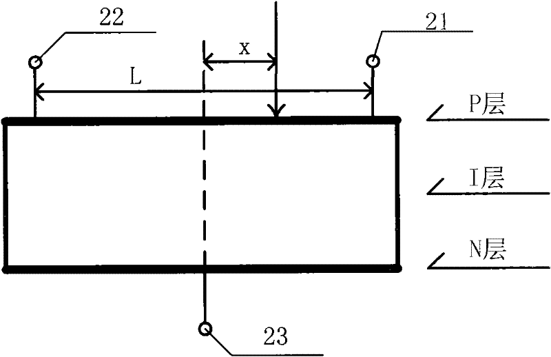
[0095] In this embodiment, the direction sensor can specifically be a PSD. In this embodiment, when the photosensitive surface of the PSD is completely irradiated by light, the PSD has no output, and when a part of the photosensitive surface of the PSD is not irradiated by light, a dark In the case of a dot area, the PSD outputs continuous position information of the dark dot area on its photosensitive surface. When calculating the position information of the dark dot area, the three relational expressions in the second embodiment of the touch screen can be used, which will not be repeated here.

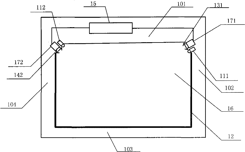
[0096] Such as Figure 6 As shown, it is a schematic structural diagram of the fourth embodiment of the touch screen of the present invention, and Figure 5 The difference of the shown schematic diagram is that this embodiment can also include a touch screen frame, the touch screen frame surrounds the touch detection area 16 , and the touch screen frame includes a first edge 101 , a ...


PUM


Abstract

The invention relates to a touch screen, a touch system and a display. One of the touch screens includes at least two light sources installed around the touch detection area of ​​the touch screen, and the light emitted by each light source covers the touch detection area; a light-absorbing strip is installed around the touch detection area, and the light-absorbing strip absorbs the light emitted by at least two light sources ; At least two direction sensors are respectively installed adjacent to at least two light sources, each direction sensor has at least one light source; at least two light-collecting devices are installed in front of at least two direction sensors, each direction sensor has a front At least one light concentrating device, the light concentrating device gathers the light reflected by the touch object to the direction sensor; the processing circuit is connected with at least two direction sensors. The invention can improve the position resolution of the touch screen.

Description

technical field [0001] The invention relates to the field of optoelectronic technology, in particular to a touch screen, a touch system and a display. Background technique [0002] With the popularization of computer technology, a new human-computer interaction technology—touch screen technology emerged in the early 1990s. With this technology, the user can operate the computer as long as he gently touches the graphics or text on the computer display screen, thus getting rid of the shackles of the keyboard and mouse, which greatly facilitates the user. [0003] The commonly used touch screen in the prior art is an infrared touch screen. The infrared touch screen uses a large number of one-to-one corresponding infrared emitting tubes and infrared receiving tubes to determine the position information of the touched object, and the principle is relatively simple. [0004] However, the infrared touch screen has the following defects: due to the use of a large number of infrared...

Claims


Application Information

Patent Timeline
Patent Type & Authority Applications(China)
IPC IPC(8): G06F3/042
Inventor 刘建军叶新林刘新斌
Owner BEIJING UNITOP NEW TECH CO LTD
Why Eureka
Try Eureka